Device For Active Electrical Compensation

a technology of active electrical compensation and circuit, which is applied in the integration of ac network to reduce harmonics/ripples, power network operation systems, etc., can solve the problems of undesirable second effects, degrade the quality of signal traveling through the network, and destroy these devices, so as to improve the quality of voltag

Active Publication Date: 2022-06-23
ECOLE NAT SUPERIEURE DE LELECTRONIQUE & DE SES APPL +1
View PDF0 Cites 2 Cited by
  • Summary
  • Abstract
  • Description
  • Claims
  • Application Information

AI Technical Summary

Benefits of technology

[0026]One aim of the invention is to “decontaminate” the current consumed by a non-linear load, by cancelling, on the network side, its harmonic content, the unbalanced content and also the reactive content of the current in the aim of improving the quality of the voltage on the electrical network side. This invention, having a 4-wire structure, is adapted to the harmonic spectrum containing the conventional orders (5, 7, 11, 13, etc.) of industrial areas as well as those of third order and their odd multiples (3, 9, 15, etc.) of residential, commercial or administrative areas.

Problems solved by technology

The switching frequencies of the electronic power components of the inverters generally use high-frequency harmonic components in the signal injected into the network, which degrades the quality of the signal traveling through the network.
However, this auxiliary filter 6 can cause undesirable second effects such as resonance with other passive elements installed on the electrical network 1.
These electrical resonance phenomena in some cases lead to voltage or amperage peaks greatly above the values permissible by the apparatuses connected to the network 1 and cause the destruction of these devices.
This auxiliary filter also gives rise to an active power consumption by its damping resistance.
In addition, the filtering quality of these auxiliary filters degrades over time because of the aging of their passive components.

Method used


Image

  • Device For Active Electrical Compensation
  • Device For Active Electrical Compensation
  • Device For Active Electrical Compensation

Examples


Embodiment Construction

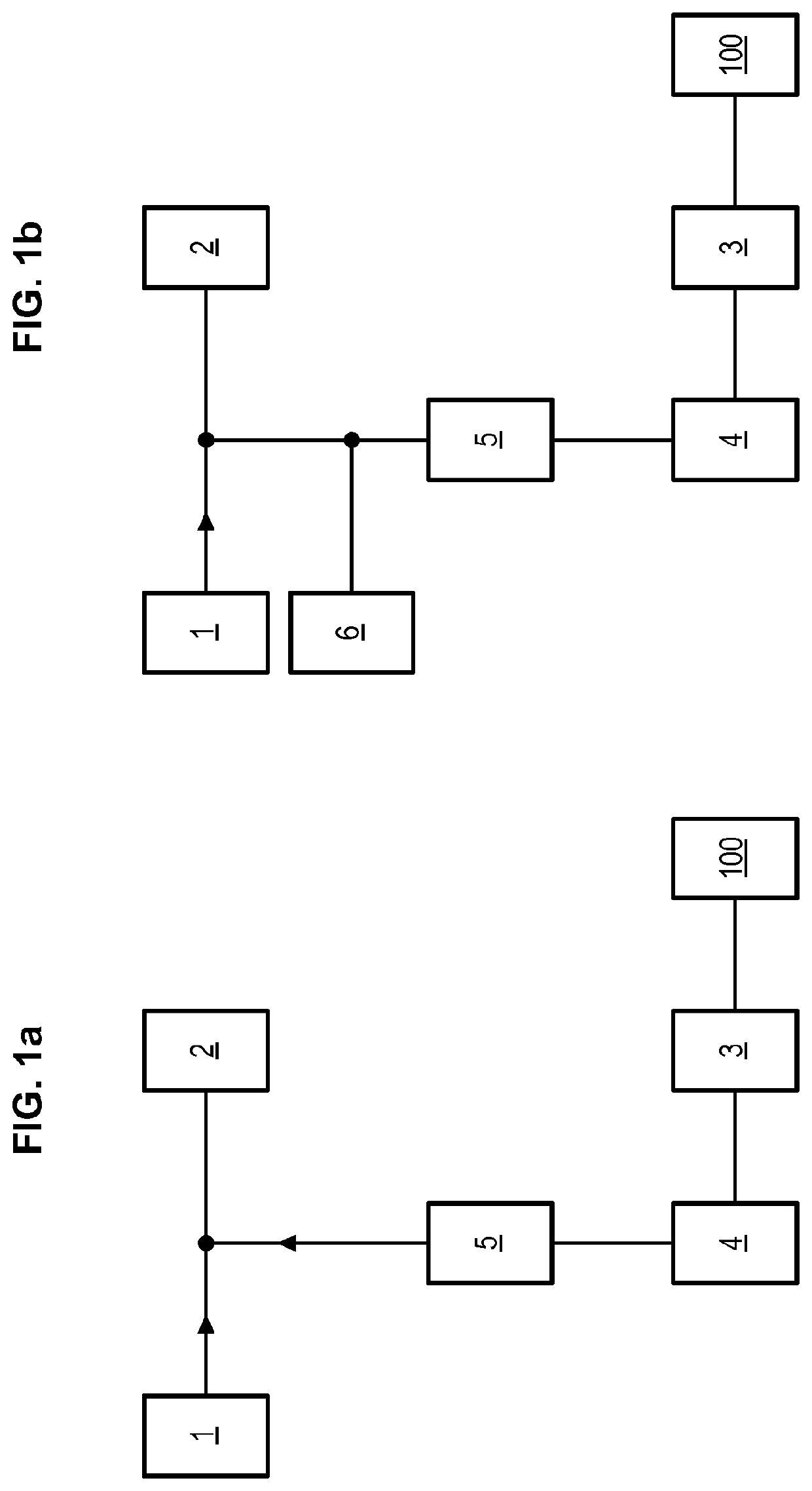
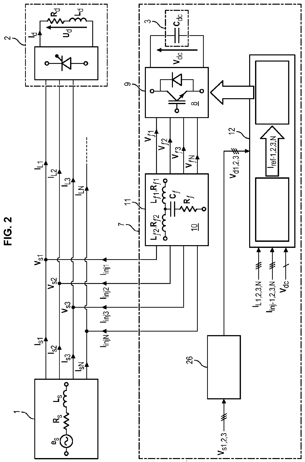
[0125]The invention relates to an electrical system as shown in FIGS. 2-3, comprising a power supply network 1 with 3 phases and one neutral, a non-linear or linear load 2 or both connected to the network 1, a capacitive energy storing element 3, a renewable-energy-generating power unit 100 and a compensating assembly 7 connected on the one hand to its input, downstream, to the output of the renewable-energy-generating power unit 100 associated with the storing element 3 and on the other hand shunt-connected across its output, upstream, at a connection point (C) located between the network 1 and the load 2.

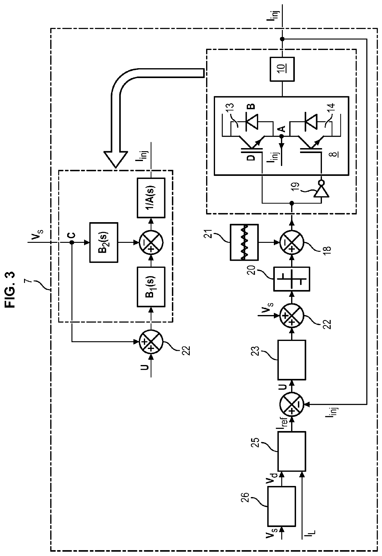
[0126]The compensating assembly 7 includes:[0127]a power converting unit 8, including an inverter 9, generating an AC current with a frequency band ranging from 50 to 2500 Hz, covering:

[0128]a) the whole frequency band of the non-active disturbance current which has: all or part of the harmonics, and at the fundamental frequency all or part of the reactive power and / or unbalanced ...


PUM


Abstract

The invention relates to a current-compensating device able to be connected, in shunt configuration, between an electrical network and non-linear and linear electrical loads and downstream of at least one renewable-energy-generating power unit coupled to an energy-storing element, the compensating device including:
    • a power converting unit including at least one voltage inverter able to generate an AC current;
    • an output filtering unit, including one filter dimensioned to block the harmonic components due to the switching of the inverter;
    • a control unit comprising a unit for computing reference currents and a switch driving device that controls the switching of the inverter as a function of the identification of the currents by the unit for computing the reference currents.

Description

[0001]The invention relates to the general field of power electronics and its applications on electrical power distribution networks or on-board electrical power networks, smart buildings and micro-grids, and more specifically modules for filtering and compensating electrical networks with injection of power from renewable sources.[0002]It is well known that the quality of the electrical signal delivered by the distribution network has a direct consequence on the performance of the systems powered by this network, as well as the lifetime of the items of electrical equipment that constitute the network or are connected to it.[0003]In particular, harmonic distortion, a phase difference between the voltage and the amperage, i.e. the reactive power, and also current and voltage unbalance are factors used to express the quality of the energy travelling through this network.[0004]The term “unbalance” is understood to mean a difference in the physical quantities of the signal between the d...

Claims


Application Information

Patent Timeline
Patent Type & Authority Applications(United States)
IPC IPC(8): H02J3/01H02J3/14H02J3/18H02J3/38H02M1/12
CPCH02J3/01H02J3/14H02J3/1842H02J2300/28H02M1/12H02J2300/24H02J3/381H02J3/1821H02J2310/12H02J2310/14H02J2300/26Y02E10/56Y02P80/10Y04S20/222Y02E40/30Y02B70/3225
Inventor ALALI, MOHAMAD ALAA EDDINSHTESSEL, YURIBARBOT, JEAN-PIERRE
Owner ECOLE NAT SUPERIEURE DE LELECTRONIQUE & DE SES APPL
Why Eureka
Try Eureka