Thermal Buoyant High Efficient System

a high-efficiency, thermal buoyant technology, applied in the direction of machines/engines, mechanical power devices, mechanical apparatus, etc., can solve the problems of incompatibility of low temperature heat sources and low temperature storage systems, high temperature requirements, and high use of fossil fuels

Pending Publication Date: 2022-06-30
K C SUDARSHAN
View PDF9 Cites 0 Cited by
  • Summary
  • Abstract
  • Description
  • Claims
  • Application Information

AI Technical Summary

Problems solved by technology

These engines use fossil fuels and require high temperatures.
The reduction of an increased pressure in the boiler for using the low temperature sources despite rise in pressure and the rise in boiling point due to increased height and pressure is not facilitated by the system that makes the system incompatible for low temperature heat sources and low temperature storages.
Height and other pressurizing mec

Method used


Image

  • Thermal Buoyant High Efficient System
  • Thermal Buoyant High Efficient System
  • Thermal Buoyant High Efficient System

Examples


Embodiment Construction

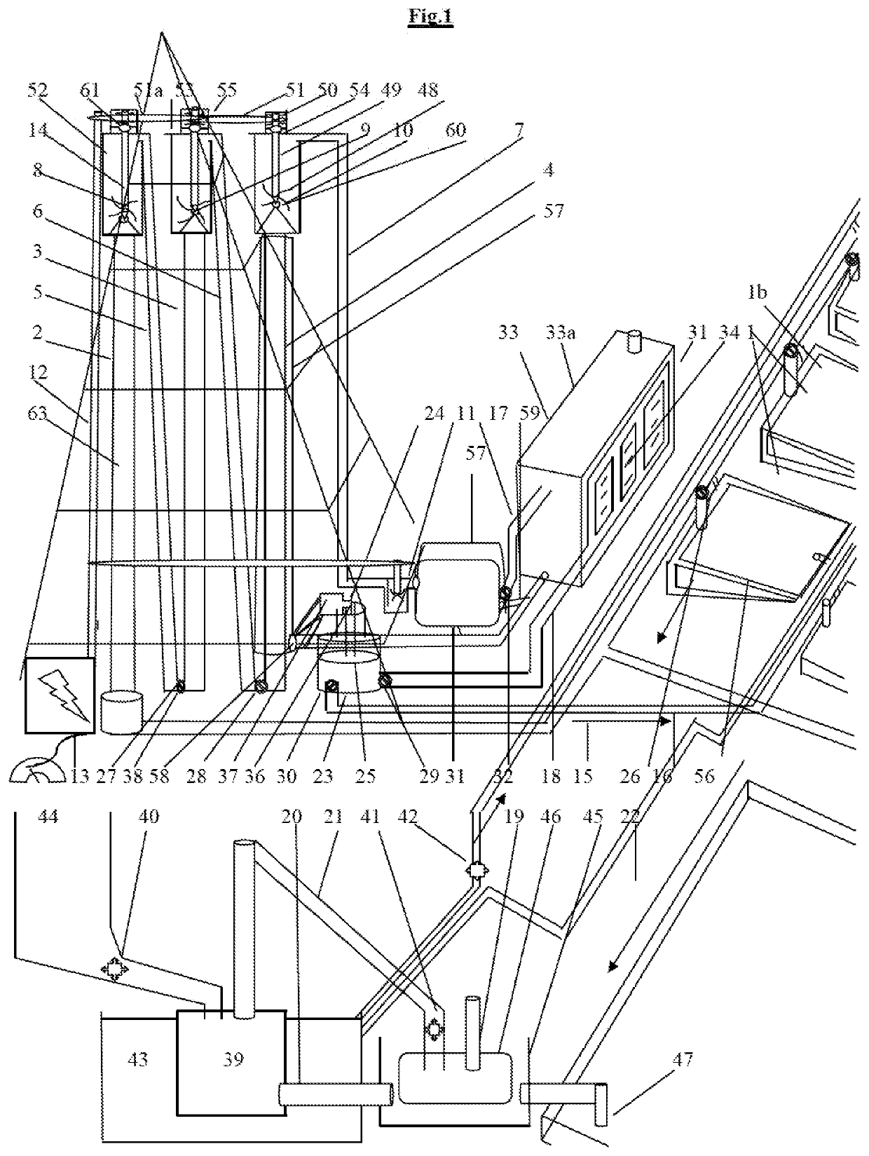
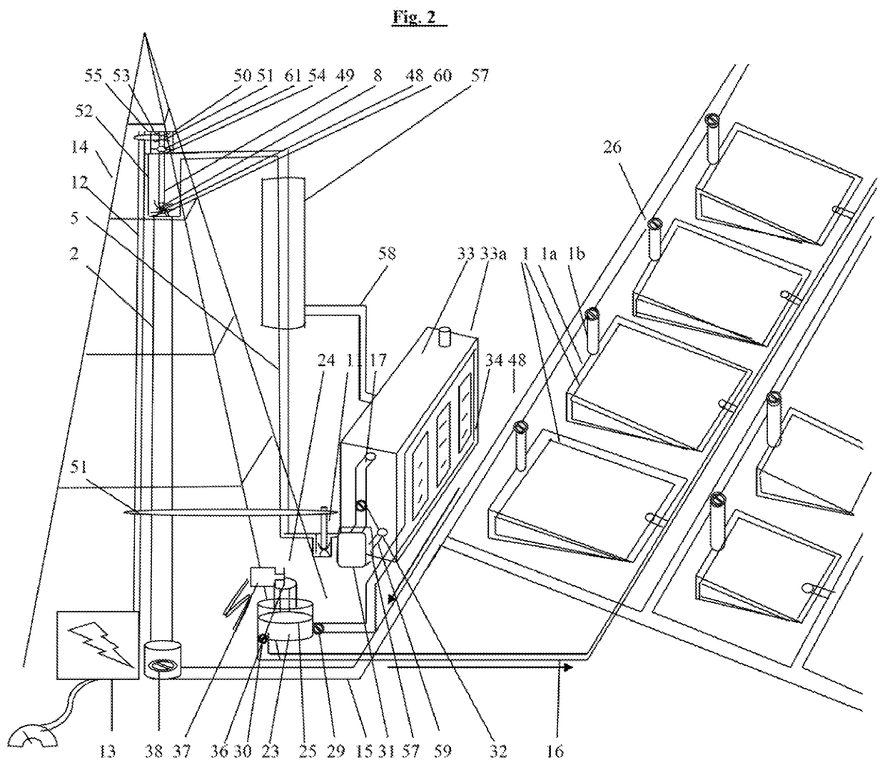
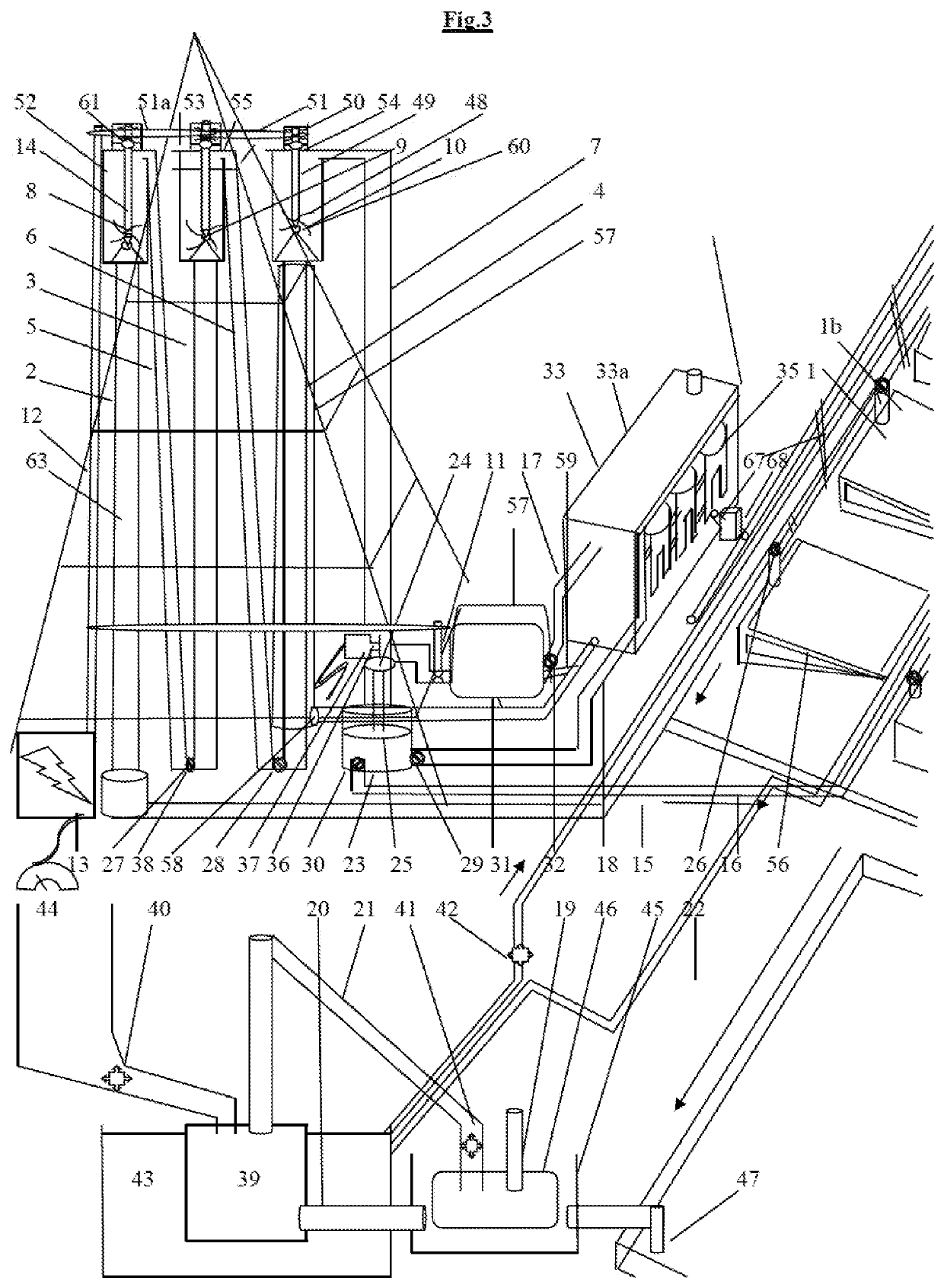
[0031]The invention uses the following parts / items:

[0032]Boiler 1,

[0033]Boiler cover 1a,

[0034]Vertical pipe 1b,

[0035]Liquid Chamber 2, 3, 4,

[0036]Gas Chamber 5, 6, 7

[0037]Liquid Turbine 8, 9, 10,

[0038]Gas Turbine 11,

[0039]Axle 12,

[0040]Alternator 13,

[0041]Tower or stand 14,

[0042]Vapor output pipe / horizontal pipe 15,

[0043]Liquid In Pipe 16,

[0044]Condenser In pipe 17,

[0045]Condenser out pipe 18,

[0046]Water In pipe 19,

[0047]Water Out Pipe 20,

[0048]Water pipe 21,

[0049]Hot water circulation pipe 22

[0050]Liquid Re-input Section 23

[0051]Washer 24, 25,

[0052]Vapor-Liquid phase valve 26,

[0053]Chamber Valves 27, 28,

[0054]Liquid Input Valve 29,

[0055]Liquid Output Valve 30,

[0056]Cylinder 31

[0057]Cylinder valve (pressure control / regulation valve) 32,

[0058]Condenser 33,

[0059]Container 33a,

[0060]Multiple-pipes 34,

[0061]Drums 35,

[0062]Pusher with switching mechanism 36,

[0063]Compressor / motor 37,

[0064]Pressure valves 38, 38a,

[0065]Heat generation tank 39,

[0066]Motors 40, 41, 42,

[0067]Hot water re...


PUM


Abstract

A system for the generation of mechanical or electrical energy from heat energy, where increasing a height or pressure in a liquid chamber of the system containing a liquid increases an efficiency of the system up to a hundred percent or increases such efficiency until a critical temperature or pressure of the vapor (gas) is reached at the bottom of liquid chamber or in the boiler of the system depending upon the increment in height, pressure and the type of liquid used in the system. An increase in height of the system for such increased efficiency can be adjusted to a smaller height by maintaining a series of liquid and gas chambers where the vapor flows through the series of chambers or by adding pressure valves. The heat energy from high to low temperature sources can be convened to mechanical and electrical energy.

Description

FIELD OF INVENTION[0001]The invention relates to the system that converts heat energy from sources of high temperatures and low temperatures (as low as room temperature) to electrical energy with a high efficiency of up to 100 percent or increases such efficiency until a critical temperature or pressure of the vapor (gas) is reached at the bottom of liquid chamber or in the boiler of the system. The buoyancy force is used as a kinetic force where vapor from boiler is accelerated in the liquid medium on the liquid pipes and runs the turbine at the top of the liquid pipes at the enlarged part. The increasing height of the liquid pipes or the increasing number of pipes in case of multiple liquid chambers increases the efficiency up to hundred percent or until critical temperature or pressure of the vapor is reached in the boiler or bottom of liquid chamber. Depending upon the liquid used in the boiler and in liquid chamber, a system with different height of liquid chamber or different ...

Claims


Application Information

Patent Timeline
IPC IPC(8): F03G7/05F01K27/00F03G6/06
CPCF03G7/05F01K23/10F03G6/063F01K27/005F01K25/065F03G4/001F03G4/035F03G4/063F03G6/004F03G6/005F03G6/071F03G6/127F03G6/083F03B17/02Y02E10/20
Inventor K.C., SUDARSHAN
Owner K C SUDARSHAN
Why Eureka
Try Eureka