Thermal energy storage

Pending Publication Date: 2022-07-14
SIEMENS GAMESA RENEWABLE ENERGY GMBH & CO KG
View PDF0 Cites 0 Cited by
  • Summary
  • Abstract
  • Description
  • Claims
  • Application Information

AI Technical Summary

Problems solved by technology

These streams can both stress the materials (mechanical stress) and create a non-uniform temperature profile in the storage.
Such a pattern reduces the convection in the storage but at the same increases the pressure losses during charging and discharging of the storage.
Moreover, this pattern cannot provide a uniform temperature distribution in the thermal energy storage during the standstill pe

Method used


Image

  • Thermal energy storage
  • Thermal energy storage

Examples


Embodiment Construction

[0048]The illustrations in the drawings are schematic. It is noted that in different figures, similar or identical elements are provided with the same reference numerals or with reference numerals which differ only within the first digit.

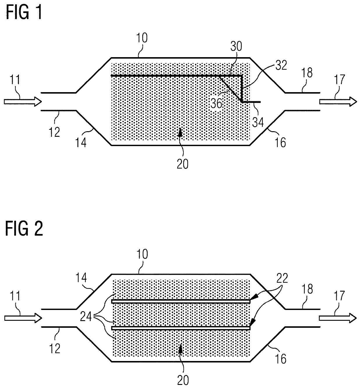
[0049]FIG. 1 shows a side-view of a known thermal energy storage arranged in a housing 10. The thermal energy storage housing 10 comprises a fluid inlet 12 for receiving a working fluid, such as water, hot or cold steam, air, nitrogen or argon, as indicated by arrow 11. The thermal energy storage housing 10 further comprises a diffuser section 14 for evenly distributing the working fluid and for reducing the flow speed of the working fluid. The thermal energy storage further comprises thermal storage elements, such as bricks, stone, lava stone, granite, basalt or ceramics provided as bulk material within the housing 10 to form a thermal energy storage structure 20. The thermal energy storage housing 10 further comprises a nozzle section 16 for incre...


PUM


Abstract

Provided is a thermal energy storage including a housing having a fluid inlet and a fluid outlet, and a thermal energy storage structure arranged within the housing between the fluid inlet and the fluid outlet, the thermal energy storage structure including thermal energy storage elements and flexible separator elements, the flexible separator elements being arranged such that the thermal energy storage elements are separated into layers, each layer forming a channel between the fluid inlet and the fluid outlet. Furthermore, a method of manufacturing a thermal energy storage and a power plant for producing electrical energy is provided.

Description

CROSS-REFERENCE TO RELATED APPLICATIONS[0001]This application claims priority to PCT Application No. PCT / EP2020 / 069225, having a filing date of Jul. 8, 2020, which is based off of EP Application No. 19185124.5, having a filing date of Jul. 9, 2019, the entire contents both of which are hereby incorporated by reference.FIELD OF TECHNOLOGY[0002]The following relates to the field of thermal energy storages, in particular to thermal energy storages with reduced internal natural convection and a flexible channel structure. Furthermore, the following relates to a method of manufacturing such a thermal storage and to a power plant for producing electrical energy.BACKGROUND[0003]Thermal energy storages play an important role in the improvement of the stability of power supply networks and for increasing the energy efficiency. There are different types of thermal energy storages depending on how the energy is stored (using heat capacity of a material or using phase change enthalpy or even us...

Claims


Application Information

Patent Timeline
IPC IPC(8): F28D20/00
CPCF28D20/00F28D2020/0069F28D2020/0091F28D20/0056Y02E60/14
Inventor PAGELSEN, NIELSWAGNER, JENNIFER VERENAEGGERS, JAN RUDOLFZACZEK, ALEXANDER
Owner SIEMENS GAMESA RENEWABLE ENERGY GMBH & CO KG
Why Eureka
Try Eureka