An optical microscope

a microscope and optical technology, applied in the field of optical microscopes, can solve the problems of low signal intensity, difficult operation, and large user knowledge of instruments

Pending Publication Date: 2022-07-21
SMI DRUG DISCOVERY LTD
View PDF0 Cites 0 Cited by
  • Summary
  • Abstract
  • Description
  • Claims
  • Application Information

AI Technical Summary

Benefits of technology

[0014]Examples described herein provide a method for preparing samples and the subsequent imaging of molecular interactions using a fully automated confocal super-resolution plus super-resolution wide-field instrument designed for high temporal resolution. All of the functions for sample preparation, image capture and image analysis are fully automated via computer control. In this way, the optical microscope is simple to operate.
[0050]The image sensor is a device that detects light signals, such as the photon streams emitted by fluorescently labelled reference elements or target elements. Such sensors may include EMCCD cameras, CCD cameras, CMOS cameras or APDs (coupled with a laser scanner) which are used for both image acquisition of the reference element and target element. Image capture of both elements enables them to be viewed, taken or saved from the sensor and the position of each element may be known with nanometer precision in two dimensions that are commonly referred to as the X- and Y-planes. Z-sections of thicker samples, such as cells, are constrained by the diffraction limit in the Z-plane. Frame-to-frame drift correction may be performed in the X-plane and Y-plane. Comparing and correcting sequences of images over extended periods of time using positional information from the reference element may be gathered both before and after the image being corrected at a specific time point. This provides a method by which the target element may be accurately rendered without distortion from movement.

Problems solved by technology

However, as much of the light from sample fluorescence is blocked at the pinhole, there is low signal intensity and so a sensitive detector such as a photomultiplier tube or avalanche photodiode are used.
However, the instruments are often complex, are often built in-house, and require considerable user knowledge to operate.
In addition, movements within the resultant images can compromise precision, and become an increasing challenge as the magnification is raised.
Monitoring kinetic properties is critical, but often based on limited macroscopic measurements.
Techniques such as single-channel patch clamp go some way towards monitoring the properties of single molecules, but are composite measurements of both ligand binding and a functional response, and can only be used for receptors that are functionally coupled to ion channels.
Current pharmokinetic models for drug metabolism are also based entirely on macroscopic kinetics experiments and crude deterministic kinetic models, devoid of the actual stochastic molecular detail of the enzymes, receptors or other samples; resulting in numerous promising drugs never reaching clinical trials.

Method used


Image

  • An optical microscope
  • An optical microscope
  • An optical microscope

Examples


Embodiment Construction

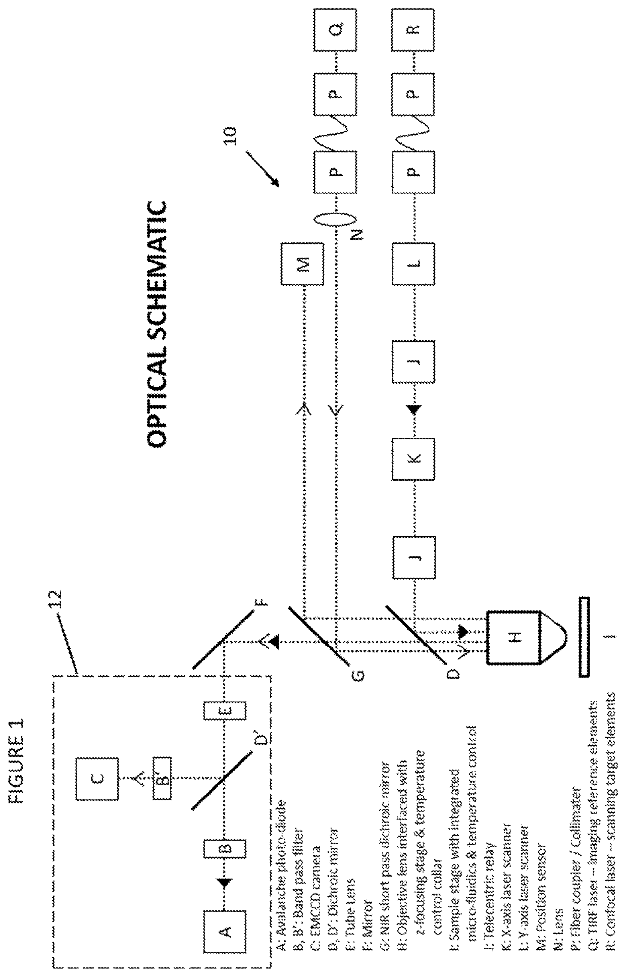
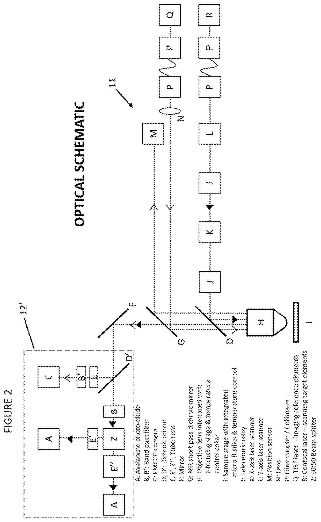
[0067]An example optical microscope 10 will now be described with reference to FIG. 1.

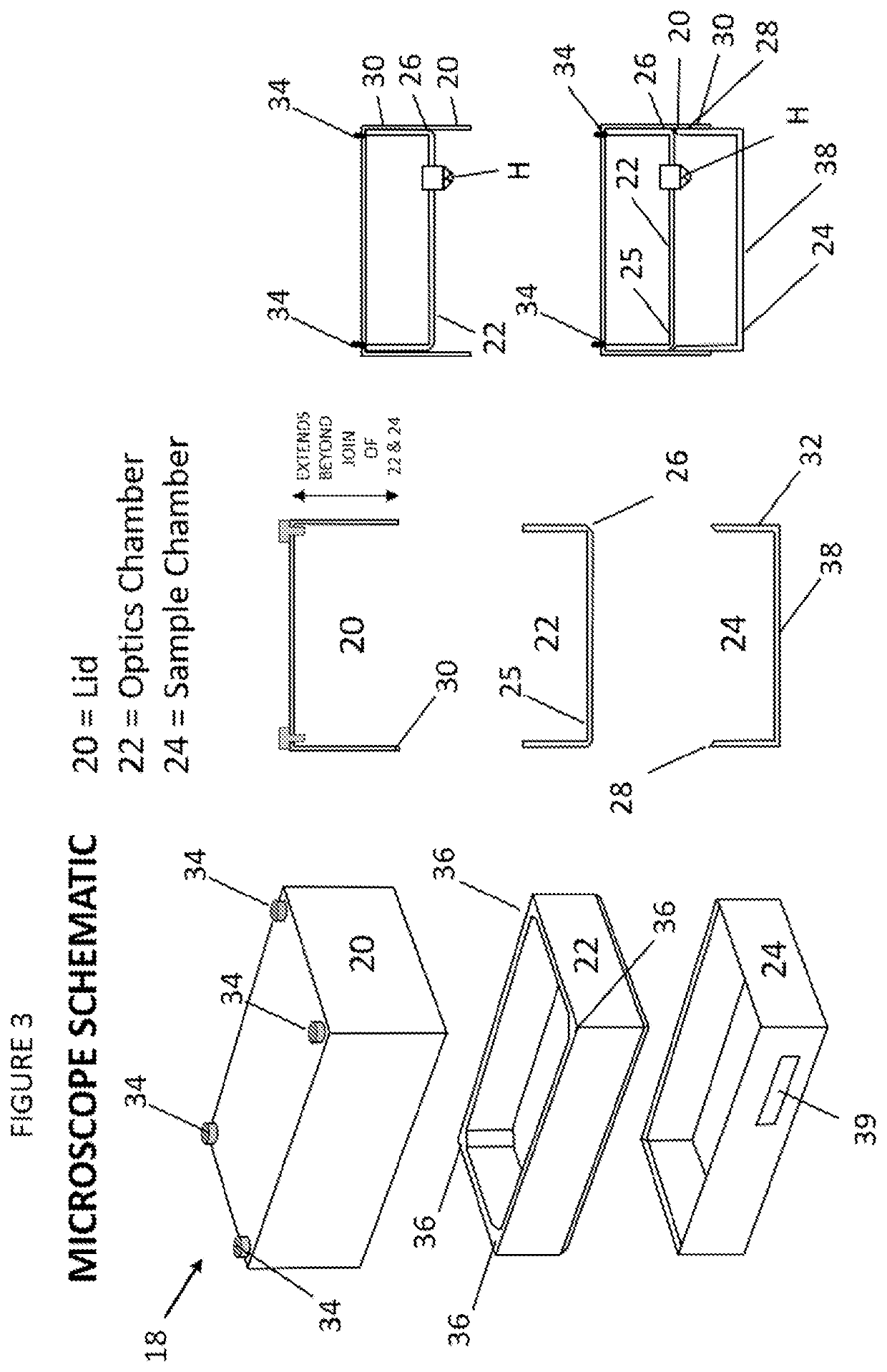
[0068]As explained in more detail below, the optical microscope 10 has a confocal microscope and a TIRF microscope as an integral part of the same device. The optical microscope is housed in a single housing. The single housing is in one and only one piece. It is a single unit. This provides stability. It also allows for the optical microscope to be compact.

[0069]The confocal microscope and the TIRF microscope simultaneously view a sample through the same objective lens H. Broadly, the TIRF microscope images reference elements of the sample for X / Y plane or horizontal plane correction and the confocal microscope scans target elements of the sample and also allows for Z or vertical axis correction.

[0070]The confocal microscope includes a confocal laser R. An optical path of the laser is then through a fiber coupler and collimator P. The optical path then continues through a laser scanner K, L that s...


PUM

PropertyMeasurementUnit
time-resolutionaaaaaaaaaa
angleaaaaaaaaaa
angleaaaaaaaaaa

Abstract

An optical microscope (10) comprising a first optical microscope (R); and a second optical microscope (Q) with a different mode of operation to the first optical microscope (R). The optical microscope (10) is configured such that the first optical microscope (R) and the second optical microscope (Q) simultaneously view a sample on a sample stage (I).

Description

FIELD OF THE INVENTION[0001]The present invention relates to an optical microscope, particularly for high resolution or super resolution microscopy, a super resolution optical microscope, a super resolution optical microscopy sample enclosure, and a sample surface.BACKGROUND OF THE INVENTION[0002]Microscopes are instruments that allow things to be seen that are too small to be seen by a human eye. Optical microscopy is a microscopy technique that uses light to produce an image. Optical microscopes are available that operate in different modes. That is to say, while they all use light to capture magnified images of small objects, the underlying methodology is different. For example, the basic types of optical microscopes are simple microscopes that use a single lens for magnification, and compound microscopes that use a plurality of lenses. In a compound microscope, a so-called objective lens close to the object being viewed is used to collect light. This provides the viewer with an ...

Claims


Application Information

Patent Timeline
Patent Type & Authority Applications(United States)
IPC IPC(8): G02B21/00
CPCG02B21/0072G02B21/0076G02B21/0032G02B21/18G02B21/34G02B21/367G02B21/0036
Inventor BROZIK, JAMES ALANTHOMPSON, ANDREW JAMES
Owner SMI DRUG DISCOVERY LTD
Why Eureka
Try Eureka