
Electrode for fuel cell having high durability, method for manufacturing same, and membrane-electrode assembly comprising same

Pending Publication Date: 2022-08-18
KOLON IND INC
View PDF0 Cites 0 Cited by
  • Summary
  • Abstract
  • Description
  • Claims
  • Application Information

AI Technical Summary

Benefits of technology

This patent relates to a new method of improving the durability of electrodes for fuel cells. The method involves using a special slurry containing a chelating agent to prevent the agglomeration and precipitation of metal catalyst particles. The chelating agent helps to capture and return metal ions to their original position in the environment, reducing dissolution and migration of the metal catalyst. This results in a more durable electrode for fuel cells that has a longer lifespan.

Problems solved by technology

However, the carbon shell is disadvantageous because it reduces the active area of the catalyst and interferes with the transfer of substances such as gas and / or water and thus decreases the output performance of the fuel cell.
In addition, the carbon shell is not economical because it requires a separate process for introducing the carbon shell.

Method used


Image

  • Electrode for fuel cell having high durability, method for manufacturing same, and membrane-electrode assembly comprising same
  • Electrode for fuel cell having high durability, method for manufacturing same, and membrane-electrode assembly comprising same
  • Electrode for fuel cell having high durability, method for manufacturing same, and membrane-electrode assembly comprising same

Examples


example 1

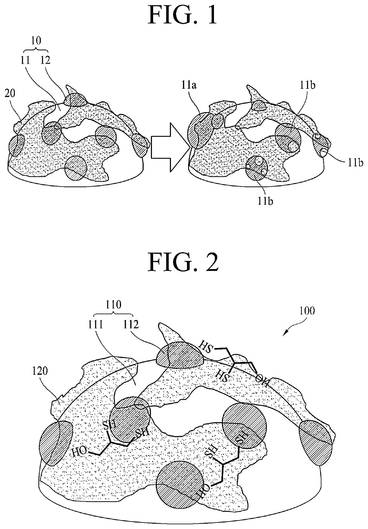
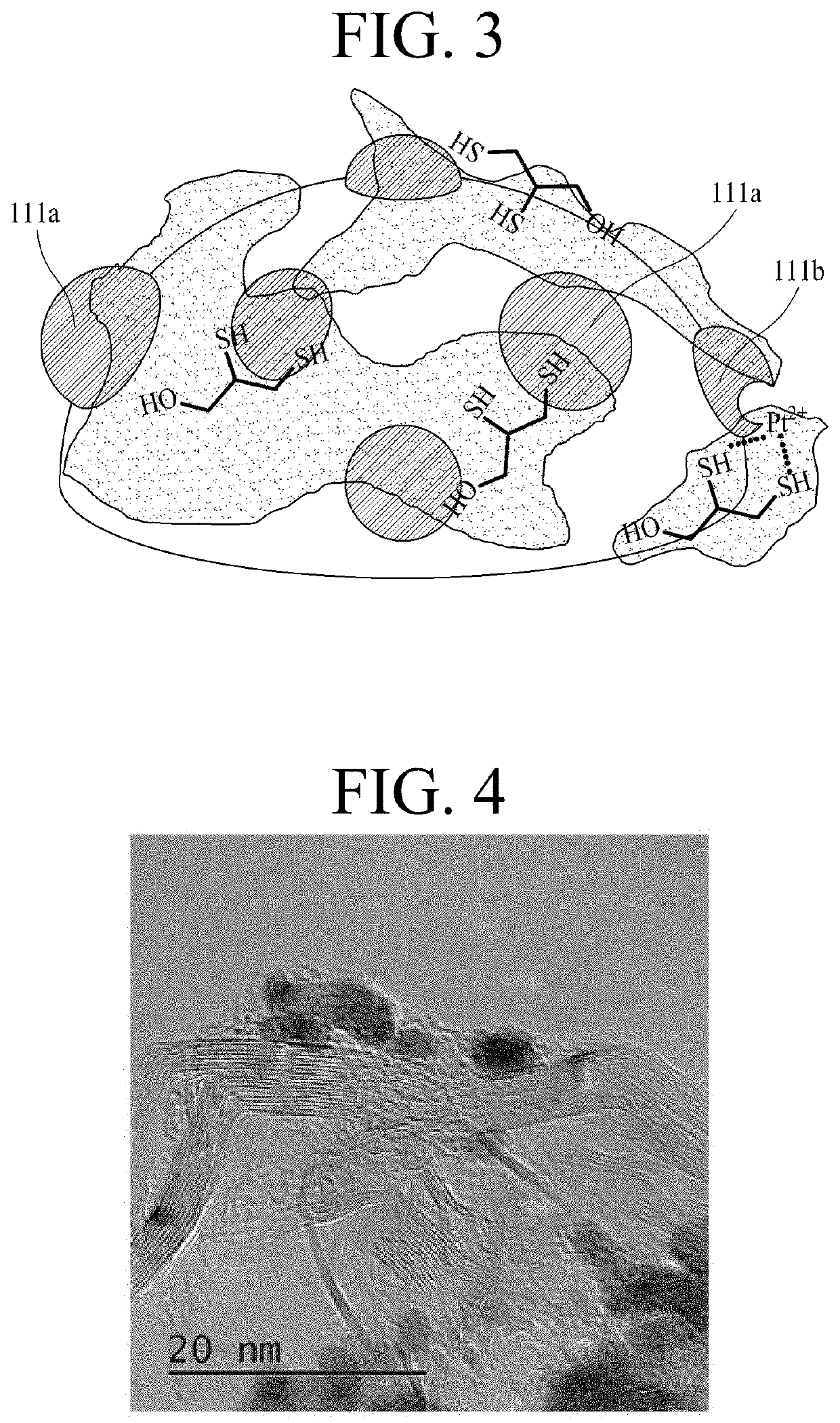
[0096]0.04 g of dimercaprol was added to 5 g of a poly(perfluorosulfonic acid) dispersion (solid content: 10 wt %), followed by mixing to homogeneity to obtain a mixture. 1 g of a Pt / C catalyst was wetted with water and then dispersed in 10 g of a dispersion medium (isopropyl alcohol) to obtain a catalyst dispersion. The mixture was mixed with the catalyst dispersion to obtain a mixed solution, and the mixed solution was dispersed using a high-pressure disperser to complete an electrode slurry.

example 2

[0097]0.04 g of dimercaprol was added to 5 g of a poly(perfluorosulfonic acid) dispersion (solid content: 10 wt %), followed by mixing to homogeneity to obtain a mixture. 1 g of a Pt / C catalyst was dispersed in 100 g of water to obtain a catalyst dispersion. The mixture was mixed with the catalyst dispersion to obtain a mixed solution, and the mixed solution was dispersed using a high-pressure disperser. The dispersed mixed solution was dried at 80° C. for 8 hours to obtain a solid, and the solid was heat-treated at 120° C. for 2 hours. The heat-treated solid was dispersed in 10 g of a dispersion medium (isopropyl alcohol) using a high-pressure disperser to complete an electrode slurry.

example 3

[0098]The catalyst dispersion obtained by dispersing 1 g of Pt / C catalyst in 100 g of water was mixed to homogeneity with 4 g of a poly(perfluorosulfonic acid) dispersion (solid content: 10 wt %) to obtain a first mixed solution. The first mixed solution was dispersed using a high-pressure disperser. The dispersed first mixed solution was dried at 80° C. for 8 hours to obtain a solid, and the solid was heat-treated at 120° C. for 2 hours. The heat-treated solid was mixed with 10 g of a dispersion medium (isopropyl alcohol) to obtain a second mixed solution. The second mixed solution was mixed with a mixture of 0.04 g of dimercaprol and 1 g of a poly(perfluorosulfonic acid) dispersion (solid content: 10 wt. %) to obtain a third mixed solution. Subsequently, the third mixed solution was dispersed using a high-pressure disperser to complete an electrode slurry.


PUM


Abstract

Disclosed are an electrode for a fuel cell, a method for manufacturing same, and a membrane-electrode assembly comprising same, the electrode having high durability by preventing catalyst degradation due to the agglomeration, deposition, elution, and / or migration of metal catalyst particles. The electrode for a fuel cell of the present invention comprises: a catalyst comprising a carrier and metal catalyst particles supported on the carrier; and an ionomer layer coated on at least a portion of the catalyst, wherein the ionomer layer comprises an ionomer and a chelating agent.

Description

TECHNICAL FIELD[0001]The present disclosure relates to an electrode for fuel cells, a method of producing the same, and a membrane-electrode assembly including the same. More particularly, the present disclosure relates to an electrode for fuel cells having high durability by preventing catalyst deterioration due to agglomeration, precipitation, dissolution, and / or migration of metal catalyst particles, a method of producing the same, and a membrane-electrode assembly including the same.BACKGROUND ART[0002]A polymer electrolyte membrane fuel cell (PEMFC), which generates electricity using a stacked structure of unit cells, each including a membrane-electrode assembly (MEA) and a separator (also referred to as a “bipolar plate”), is drawing attention as a next-generation energy source capable of replacing fossil fuels due to the high energy efficiency and environmental friendliness thereof.[0003]The membrane-electrode assembly generally includes an anode (also referred to as a “fuel ...

Claims


Application Information

Patent Timeline
IPC IPC(8): H01M8/1004H01M4/88H01M4/86H01M4/92H01M8/1018
CPCH01M8/1004H01M4/8828H01M2008/1095H01M4/926H01M8/1018H01M4/8668H01M4/8663H01M4/921H01M2300/0082Y02E60/50H01M2300/0094
Inventor KIM
Owner KOLON IND INC
Learn More