

Light-emitting device, light-emitting appliance, display device, electronic appliance, and lighting device
Patent Information
- Authority / Receiving Office
- US · United States
- Patent Type
- Applications(United States)
- Current Assignee / Owner
- SEMICON ENERGY LAB CO LTD
- Publication Date
- 2022-08-25
Smart Images
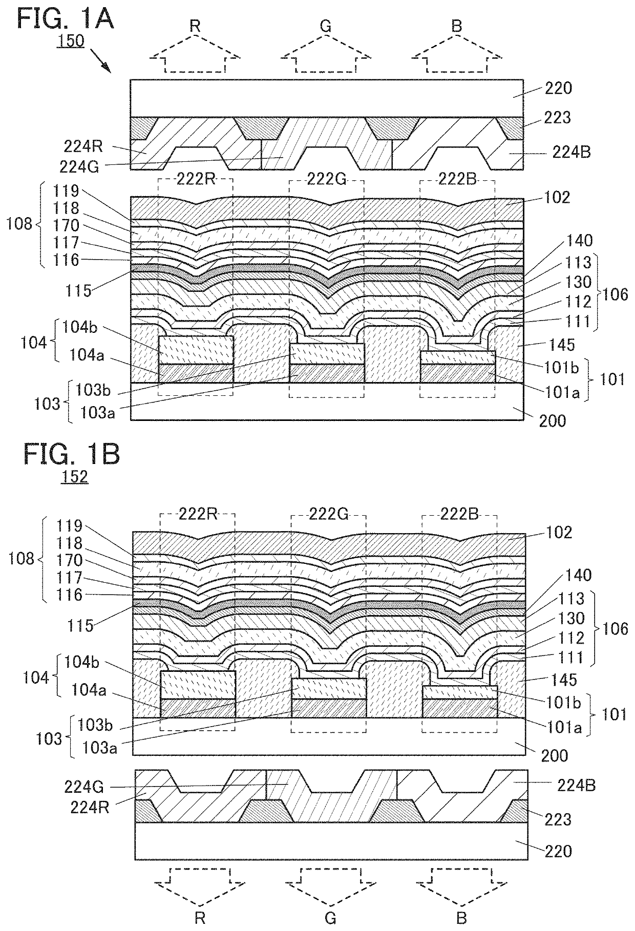
Figure 1 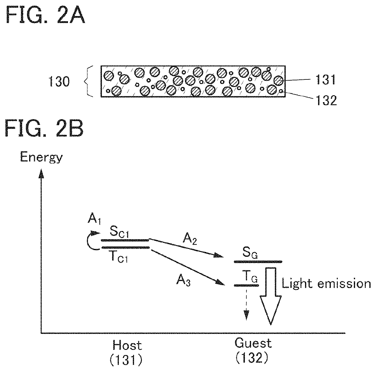
Figure 2 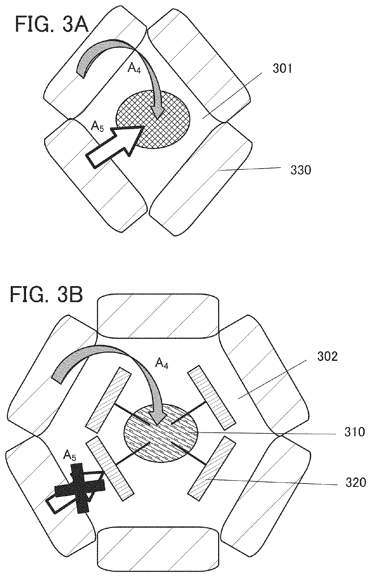
Figure 3
Abstract
Description
TECHNICAL FIELD
[0001] One embodiment of the present invention relates to a light-emitting device, or a display device, an electronic appliance, and a lighting device including the light-emitting device.
[0002] Note that one embodiment of the present invention is not limited to the above technical field. The technical field of one embodiment of the invention disclosed in this specification and the like relates to an object, a method, or a manufacturing method. Another embodiment of the present invention relates to a process, a machine, manufacture, or a composition of matter. Accordingly, specific examples of the technical field of one embodiment of the present invention disclosed in this specification include a semiconductor device, a display device, a liquid crystal display device, a light-emitting device, a lighting device, a power storage device, a memory device, a driving method thereof, and a manufacturing method thereof.BACKGROUND ART
[0003] In recent years, research and developmen...