
Percutaneous catheter

a catheter and percutaneous technology, applied in the direction of multi-lumen catheters, catheters, blood pumps, etc., can solve the problems of increased pressure loss, decreased flow rate through the circulation circuit, and inability to obtain the required circulating amount of blood, so as to reduce the pressure loss in the expansion portion, and suppress the burden on the patient's body

Pending Publication Date: 2022-09-22
TERUMO KK
View PDF0 Cites 0 Cited by
  • Summary
  • Abstract
  • Description
  • Claims
  • Application Information

AI Technical Summary

Benefits of technology

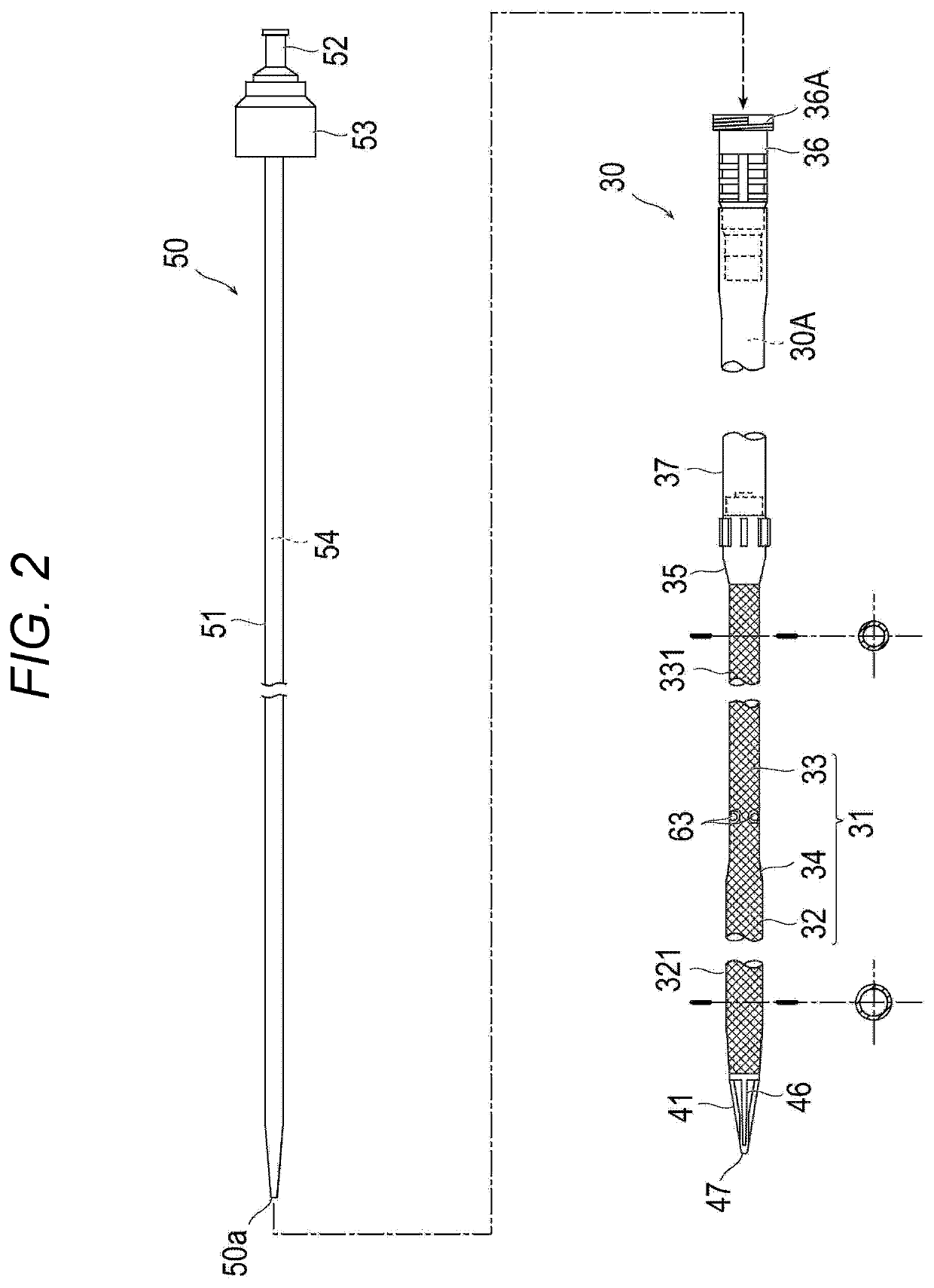
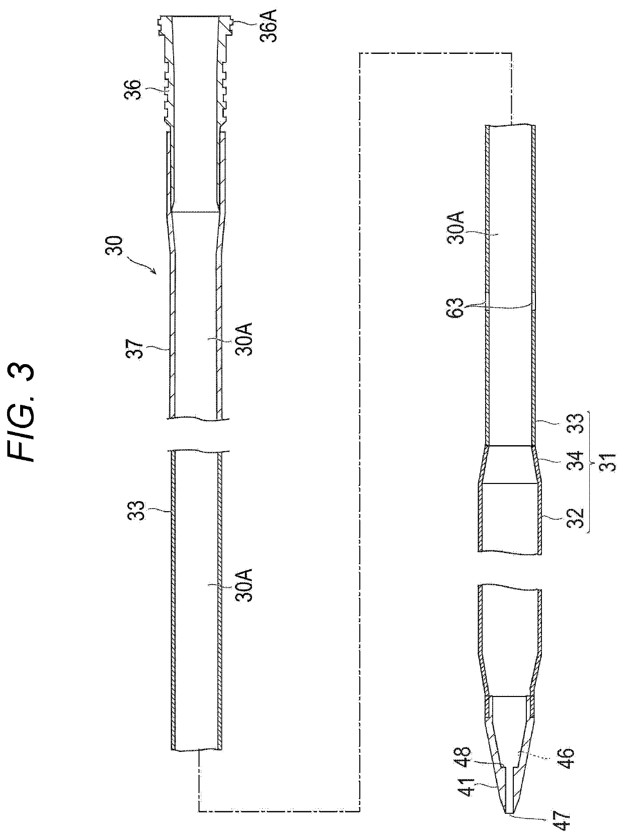
The present invention provides a percutaneous catheter that can reduce the burden on a patient's body, prevent pressure loss of liquid during circulation, and prevent tightening of a stylet. The catheter has an expansion portion, a shaft portion, and an intermediate portion. The expansion portion is designed to have higher elasticity and a smaller braiding angle, which reduces the diameter of the catheter during axial expansion. The shaft portion and intermediate portion have wires braided so as to intersect with each other. The wires are wound continuously from one portion to the next, with different characteristics. The smaller braiding angle results in a proportionally smaller amount of decrease in the diameter of the intermediate portion during axial expansion. The percutaneous catheter is inserted into a living body in a state where the expansion portion extends in the axial direction and the outer diameter is reduced, which reduces the burden on the patient's body. When the expansion portion contracts in the axial direction and returns to the original state, the required flow rate of liquid can be secured. The braiding angle of the wires in the intermediate portion is smaller, which shortens the expansion distance along the axial direction and prevents tightening of the stylet.

Problems solved by technology

However, when an inner diameter of the tube is small, the pressure loss increases, and a flow rate through the circulation circuit decreases.
Accordingly, unless the inner diameter of the tube is set to a sufficient size, a required circulating amount of blood cannot be obtained.
Consequently, when an inner diameter of a blood removal catheter (tube) or a blood supply catheter (tube) inserted into a patient's body is increased, the degree of invasion of the patient's body increases, and a burden on the patient's body increases.
This constriction of motion may impede the desired stretching of the cannula.

Method used


Image

  • Percutaneous catheter
  • Percutaneous catheter
  • Percutaneous catheter

Examples


second embodiment

[0114]A percutaneous catheter (hereinafter, referred to as “catheter”) 60 according to a second embodiment of the present invention will be described with reference to FIGS. 10 to 12. FIGS. 10 to 12 are views for explaining a configuration of the catheter 60 according to the second embodiment.

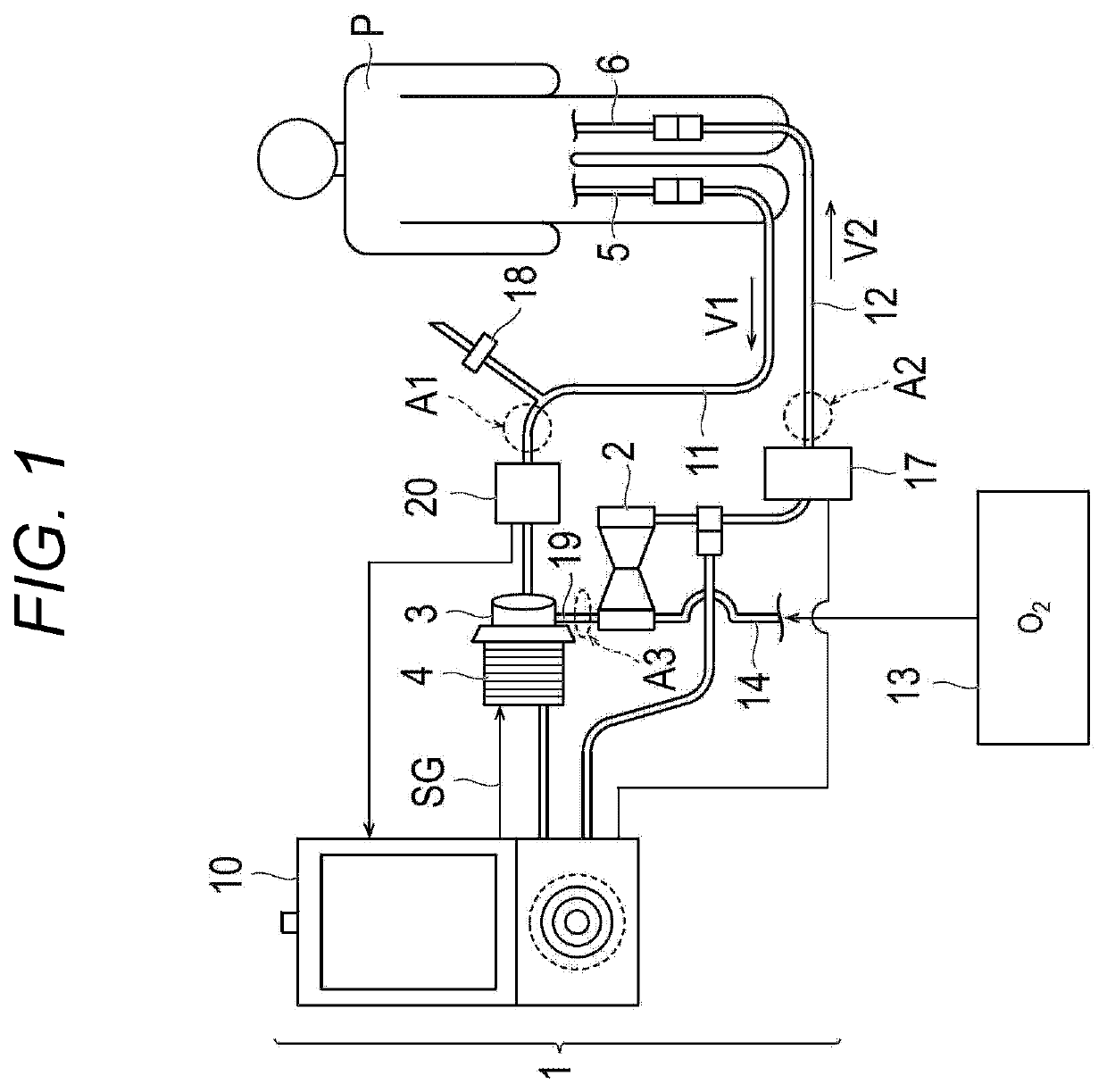
[0115]The catheter 60 is a so-called double lumen catheter, and can simultaneously perform both blood supply and blood removal. Consequently, in the present embodiment, a procedure is performed using only one catheter 60 without using two catheters of a venous side catheter (catheter for blood removal) 5 and an arterial side catheter (catheter for blood supply) 6 in the extracorporeal circulation device of FIG. 1.

[0116]As illustrated in FIGS. 10 and 11, the catheter 60 according to the second embodiment is different from the catheter 30 according to the first embodiment in that a third tube 161 including a first lumen 61 communicating with a blood supply side hole 163 has a double tube structur...


PUM


Abstract

A percutaneous catheter includes an expansion portion, a shaft portion, and an intermediate portion. The expansion portion includes a first reinforcing body including wires braided so as to intersect with each other. The shaft portion includes a second reinforcing body including the wires braided so as to intersect with each other. The intermediate portion includes a third reinforcing body including the wires braided so as to intersect with each other. The third reinforcing body is configured to have a braiding angle as an inner angle in an axial direction among angles formed by the intersecting wires which is smaller than those of the first reinforcing body and the second reinforcing body.

Description

CROSS REFERENCE TO RELATED APPLICATIONS[0001]This application is a continuation of PCT Application No. PCT / JP2021 / 006066, filed Feb. 18, 2021, based on and claiming priority to Japanese Application No. JP2020-029665, filed Feb. 25, 2020, both of which are incorporated herein by reference in their entirety.BACKGROUND OF THE INVENTION[0002]The present invention relates to a percutaneous catheter.[0003]Treatment by percutaneous cardiopulmonary support (PCPS) has been conventionally performed in order to perform cardiopulmonary resuscitation, circulatory support, and respiratory support in emergency treatment. The percutaneous cardiopulmonary support is a method of temporarily assisting and substituting for a cardiopulmonary function using an extracorporeal circulation device.[0004]The extracorporeal circulation device includes an extracorporeal circulation circuit including a centrifugal pump, an oxygenator, a blood removal path, a blood supply path, and the like, and performs gas exch...

Claims


Application Information

Patent Timeline
Patent Type & Authority Applications(United States)
IPC IPC(8): A61M1/36A61M60/113A61M60/232A61M60/38
CPCA61M1/3659A61M60/113A61M60/232A61M60/38A61M1/1698A61M60/109A61M2025/0031A61M25/005A61M2025/0024A61M25/0102A61M25/0054
Inventor YOKOYAMA, KENJI
Owner TERUMO KK
Learn More