

Method for operating an exhaust gas burner
a technology of exhaust gas burner and exhaust gas, which is applied in the direction of exhaust treatment electric control, machines/engines, separation processes, etc., can solve the problem of fuel evaporation more quickly
- Summary
- Abstract
- Description
- Claims
- Application Information
AI Technical Summary
Benefits of technology
Problems solved by technology
Method used
Image

Examples
Embodiment Construction
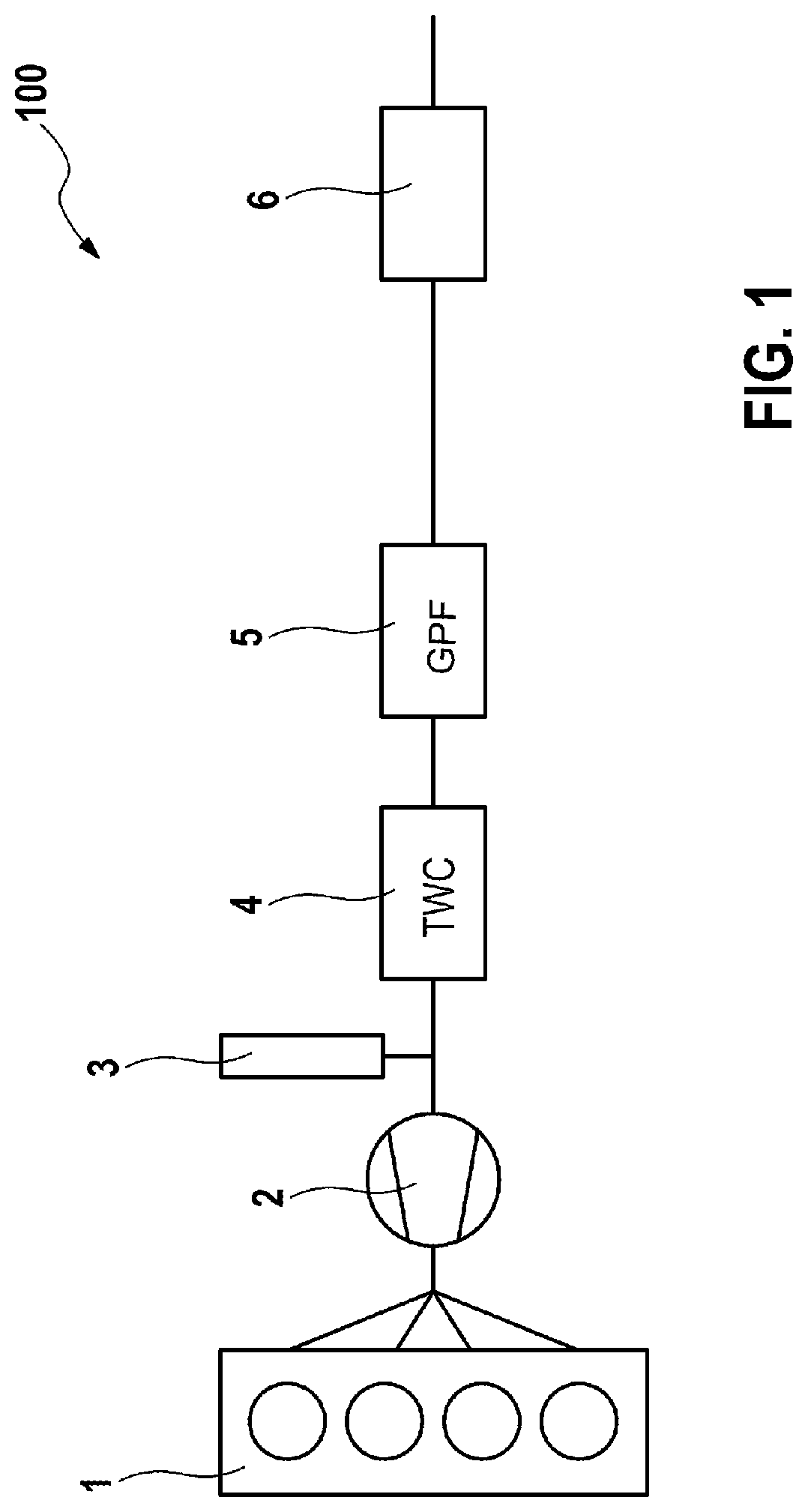
[0025]FIG. 1 shows schematically an arrangement with an internal combustion engine, an exhaust gas burner and an exhaust gas catalytic converter, of the kind that can be used in advantageous embodiments of the invention and which is denoted overall by 100.
[0026]In the example illustrated, an internal combustion engine 1 with four cylinders, a turbocharger 2 (optional), an exhaust gas burner 3, a three-way catalytic converter 4 (TWC) and a gasoline particulate filter 5 (GPF) and a muffler 6 are provided, it also being possible for further components, which are not shown here, to be provided within the scope of the invention. For example, it is also possible to provide a plurality of catalytic converters, and the arrangement of the individual components with respect to one another need not necessarily correspond to the illustrated sequence, unless stated otherwise. The decisive factor is that the internal combustion engine 1 is arranged upstream of the other components and that the ex...
PUM
 Abstract
Description
Claims
Application Information