Inline scanning holography system for phosphor and transmitter

a phosphor and transmitter technology, applied in the direction of instruments, active addressable light modulators, hologram nature/properties, etc., can solve the problems of complex electrooptical structure, system stability problems, and optical system failures, and achieve robust and stable inline scanning holography systems, high stability, and high quality

Pending Publication Date: 2022-10-06
CUBIXEL CO LTD
View PDF0 Cites 0 Cited by
  • Summary
  • Abstract
  • Description
  • Claims
  • Application Information

AI Technical Summary

Benefits of technology

[0030]According to the present invention, a high-efficiency and high-quality optical scanning holography for a transmitter or a phosphor may be implemented by forming a scanning pattern in a single optical path by using a polariza

Problems solved by technology

In addition, a bulky optical system for separating and recombining light is required, and a complex electrooptical structure for temporally and spatially modulating each of first and second beams is r

Method used


Image

  • Inline scanning holography system for phosphor and transmitter
  • Inline scanning holography system for phosphor and transmitter
  • Inline scanning holography system for phosphor and transmitter

Examples


first embodiment

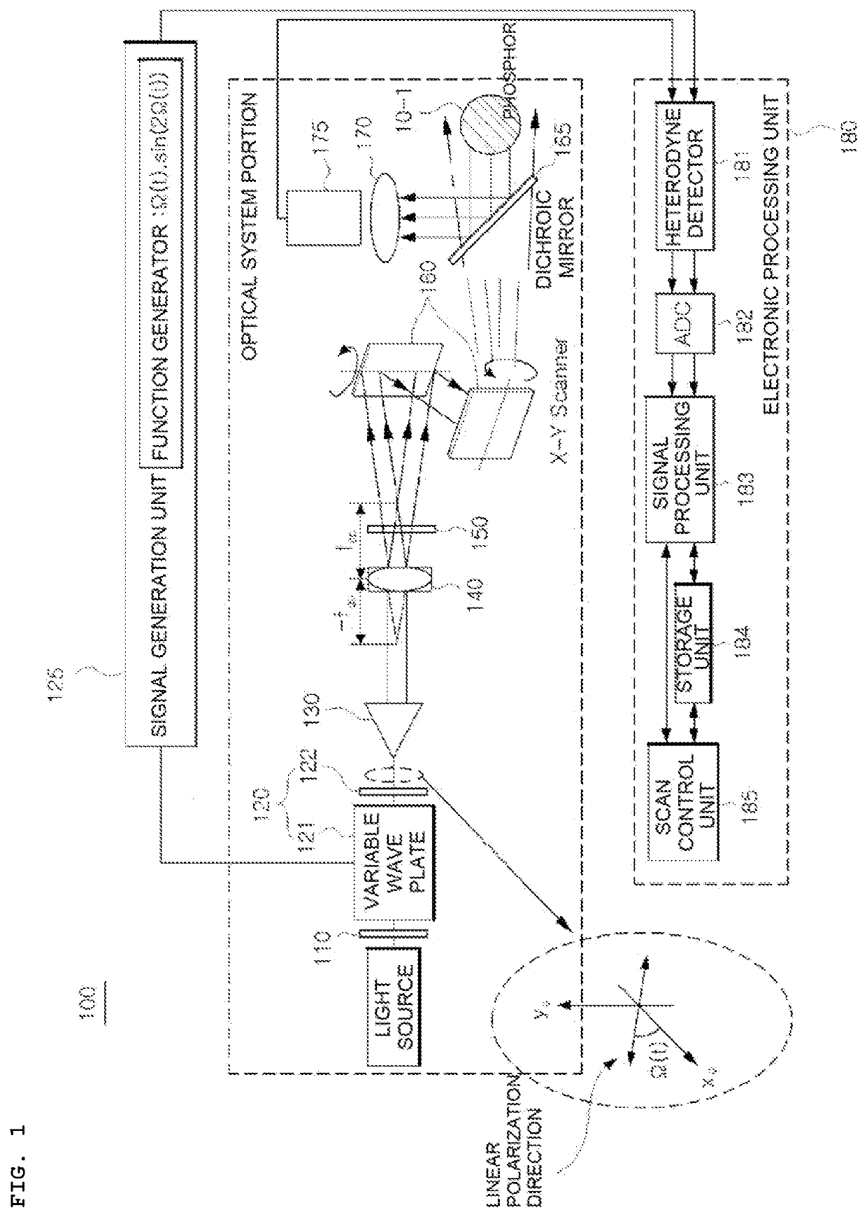
[0044]FIG. 1 illustrates an inline scanning holography system according to the present invention.

[0045]As illustrated in FIG. 1, an inline scanning holography system 100 according to a first embodiment includes a light source-side polarizer 110, a linear polarization direction converter 120, a signal generation unit 125, a collimator 130, a polarization sensitive lens 140, a polarizer 150, a scanning unit 160, a dichroic mirror 165, a first light collector 170, a first photodetector 175, and an electronic processing unit 180.

[0046]First, a light source generates electromagnetic waves. In the embodiment of the present invention, various means such as a laser generator for outputting coherent light, a light emitting diode (LED) lamp with low coherence, and a halogen lamp with a short coherence length may be used as the light source.

[0047]The light source-side polarizer (linear polarizer) 110 converts inputted light into linearly polarized beam and provides the linearly polarized beam ...

second embodiment

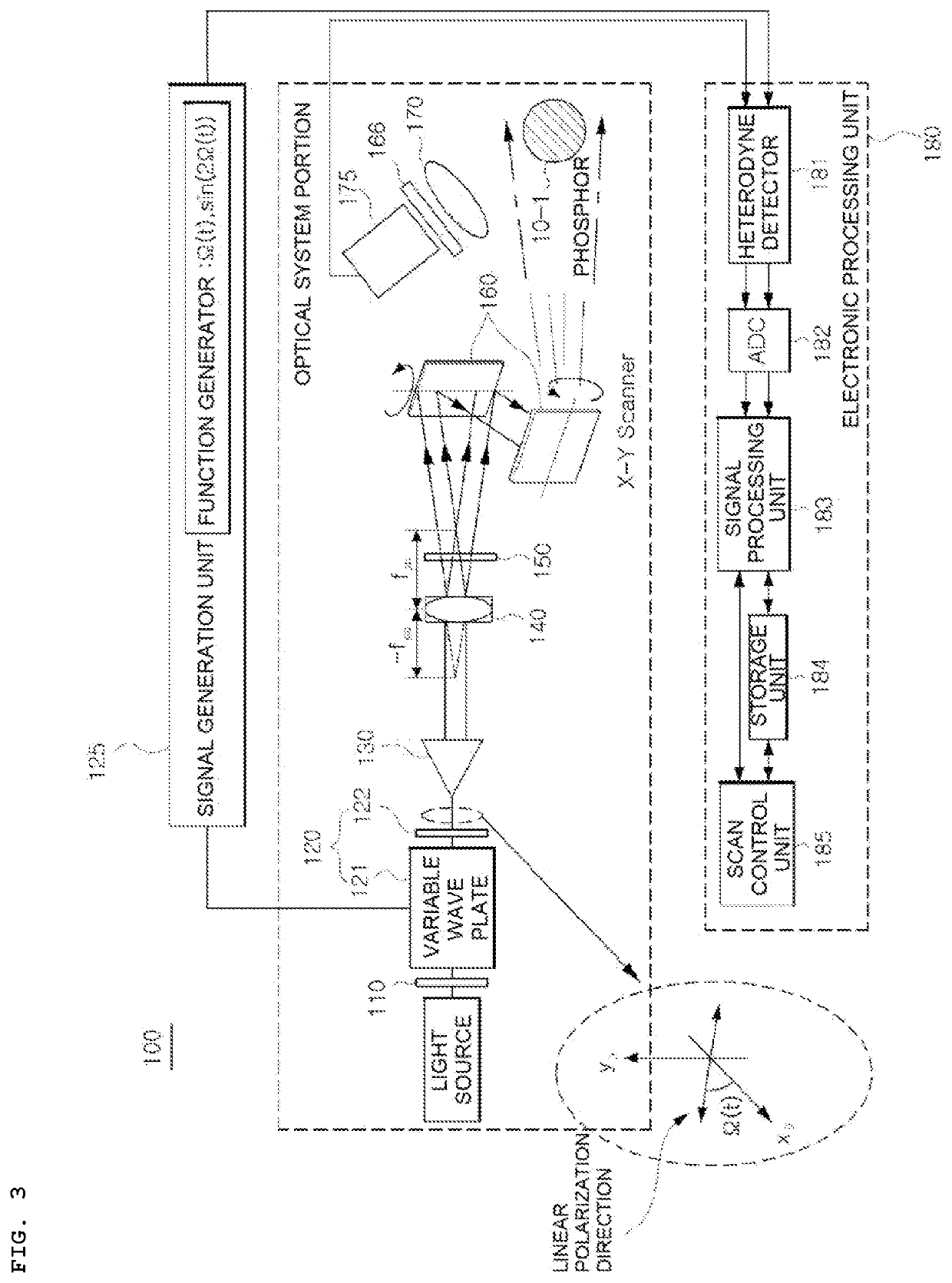
[0098]FIG. 5 illustrates the inline scanning holography system according to the present invention.

[0099]As illustrated in FIG. 5, an inline scanning holography system 200 according to the second embodiment includes a light source-side polarizer 110, a linear polarization direction converter 120, a signal generation unit 225, a collimator 130, a polarization sensitive lens 140, a polarizer 150, a scanning unit 160, a dichroic mirror 165, a first light collector 170, a first photodetector 175, and an electronic processing unit 280.

[0100]In FIG. 5, components denoted by the same reference numerals as in the first embodiment of FIG. 1 indicate that the same operations are performed thereby, and thus, redundant descriptions of the components denoted by the same reference numerals are omitted.

[0101]In FIG. 5, unlike FIG. 1, a phase modulation signal generated by the signal generation unit 225 corresponds to a phase shift signal with a phase delay value discontinuously shifted in the order...

third embodiment

[0107]FIG. 6 illustrates the inline scanning holography system according to the present invention.

[0108]As illustrated in FIG. 6, an inline scanning holography system 300 according to the third embodiment includes a light source-side polarizer 110, a linear polarization direction converter 120, a signal generation unit 125, a collimator 130, a polarization sensitive lens 140, a polarizer 150, a first lens 355, a scanning unit 160, a dichroic mirror 165, a first light collector 170, a first photodetector 175, and an electronic processing unit 180.

[0109]FIG. 6 illustrates that the first lens 355 is additionally inserted in the structure of the first embodiment of FIG. 1, and redundant descriptions of the components denoted by the same reference numerals are omitted.

[0110]In FIG. 6, the first lens 355 is placed between the polarization sensitive lens 140 and the scanning unit 160 to adjust a distance between respective focal points of the first and second spherical waves and serves as ...


PUM


Abstract

The present invention relates to an inline scanning holography system for a phosphor and a transmitter. According to the present invention, the inline scanning holography system includes a polarization sensitive lens that receives a linearly polarized beam and generates a first spherical wave of right-handed circular polarized light having a negative focal length and a second spherical wave of left-handed circular polarized light having a positive focal length, a polarizer that passes only a beam component in a predetermined polarization direction therethrough among components of the generated first and second spherical waves, a scanning unit for scanning a phosphor by using an interference beam generated between the first and second spherical waves passing through the polarizer, and a first photodetector that detects a fluorescent beam diverged from the phosphor. According to the present invention, a high-efficiency and high-quality optical scanning holography for a phosphor or a transmitter may be implemented.

Description

TECHNICAL FIELD[0001]The present invention relates to an inline scanning holography system for a phosphor and a transmitter, and more particularly, to an inline scanning holography system that may implement a high-efficiency and high-quality optical scanning holography for a phosphor or a transmitter by using a polarization sensitive lens.BACKGROUND[0002]An optical scanning-based object hologram acquisition device of the related art forms a scanning beam pattern by using an interferometric structure that spatially separates coherent light (interferable light) into a first beam and a second beam, temporally and spatially modulates the first beam and the second beam traveling in each individual optical path on the individual optical path, and recombines the first beam and the second beam.[0003]However, in the related art, in order to form a scanning pattern, an optical path difference between two separated optical paths has to be shorter than a coherence length of coherent light, and ...

Claims


Application Information

Patent Timeline
IPC IPC(8): G03H1/04
CPCG03H1/0443G03H2001/0447G03H2001/0463G03H2222/36G03H2223/22G03H2223/24G03H2225/32G03H2222/31G03H2222/24G03H2223/20G03H2223/17G03H2240/15G03H2210/42G03H2222/44G03H2222/52G03H2222/54G03H2001/0454G02B21/0048G02B21/0076G02B21/0084G02B27/286G03H1/0866G03H2001/0441G03H2001/267G02B21/14G03H1/04
Inventor KIM, TAE GEUN
Owner CUBIXEL CO LTD
Why Eureka
Try Eureka