
Electric powertrain cooling assembly and cooling assembly operating method

a technology of electric powertrain and cooling assembly, which is applied in the direction of climate sustainability, propulsion parts, vehicle sub-unit features, etc., can solve the problems of reducing fuel cell operating efficiency, presenting packaging challenges, and prone to degradation of the cooling system of the mckibben, so as to reduce the modularity of the vehicle, reduce the operating efficiency of the fuel cell, and efficiently install

Pending Publication Date: 2022-11-03
DANA HEAVY VEHICLE SYSTEMS GROUP LLC
View PDF0 Cites 0 Cited by
  • Summary
  • Abstract
  • Description
  • Claims
  • Application Information

AI Technical Summary

Benefits of technology

The invention is a vehicle system that includes a hydrogen fuel cell assembly and a traction motor. The system also includes a cooling assembly with an inlet manifold and a fan array. The cooling system is positioned over the cab of the vehicle, which reduces the risk of degradation and also increases efficiency compared to cooling systems positioned below the fuel cells. The deflector includes slats that direct airflow to the fan array, reducing power consumption and increasing cooling system efficiency. The hydrogen fuel cells and storage tanks are positioned within a frame, which increases storage capacity and also allows for increased modularity and adaptability of the fuel cell assembly. The fan array includes multiple fans that are arranged perpendicular to the vehicle's forward direction of travel, which further increases cooling system efficiency.

Problems solved by technology

However, the inventors have identified several drawbacks with McKibben's heavy duty vehicle as well as other electric vehicles.
McKibben's cooling system may be susceptible to degradation from external factors such as road debris.
Positioning the coolant modules below the fuel cell system may present packaging challenges due to the surrounding systems such as the battery assembly.
Further, the coolant modules may not achieve desired thermodynamic behavior due to their positioning, which may decrease fuel cell operating efficiency.
Still further, the inventors have recognized that positioning the coolant modules below the fuel cells and storage tanks may present challenges to efficiently installing the both the fuel cell system and the traction batteries.

Method used


Image

  • Electric powertrain cooling assembly and cooling assembly operating method
  • Electric powertrain cooling assembly and cooling assembly operating method
  • Electric powertrain cooling assembly and cooling assembly operating method

Examples


Embodiment Construction

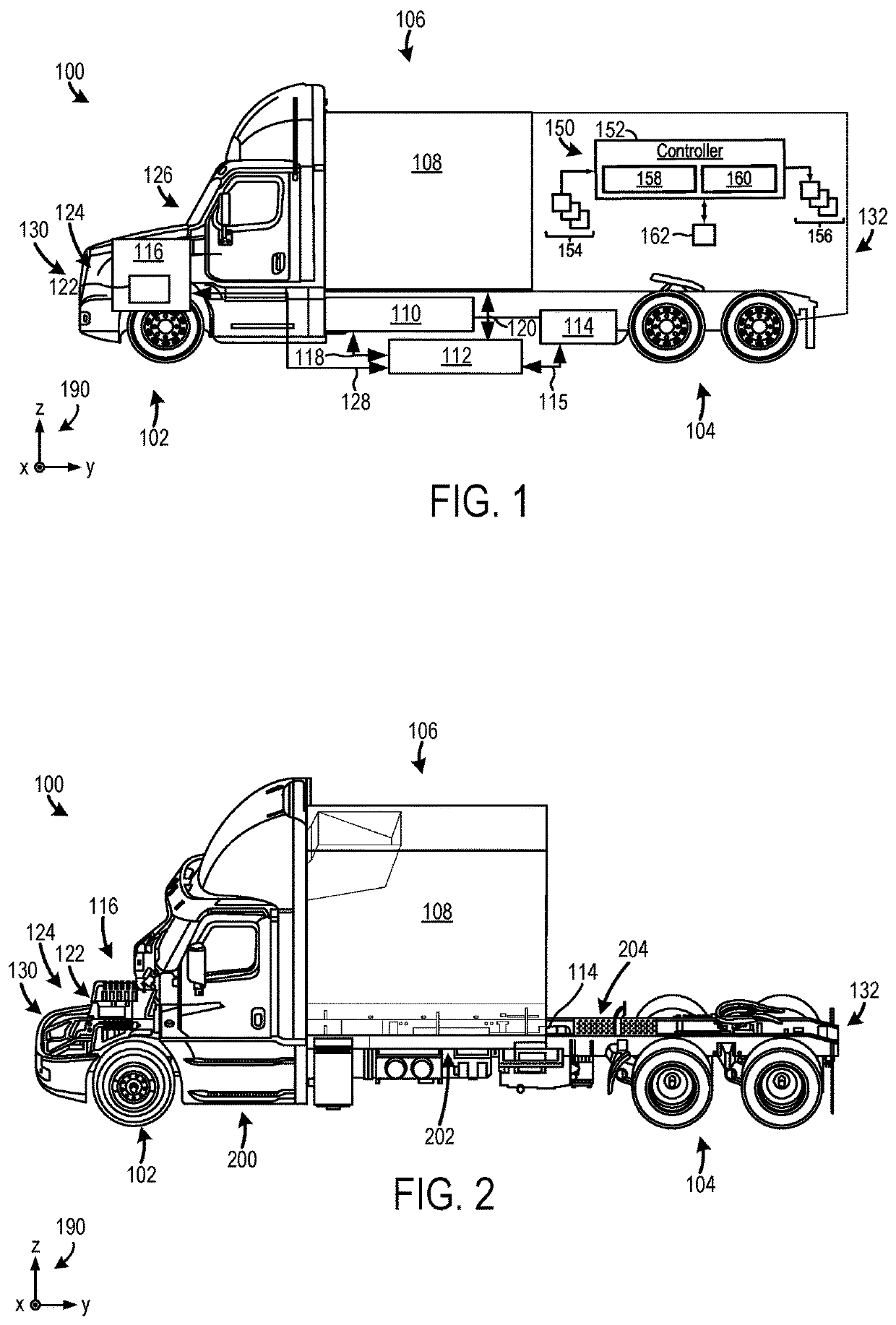
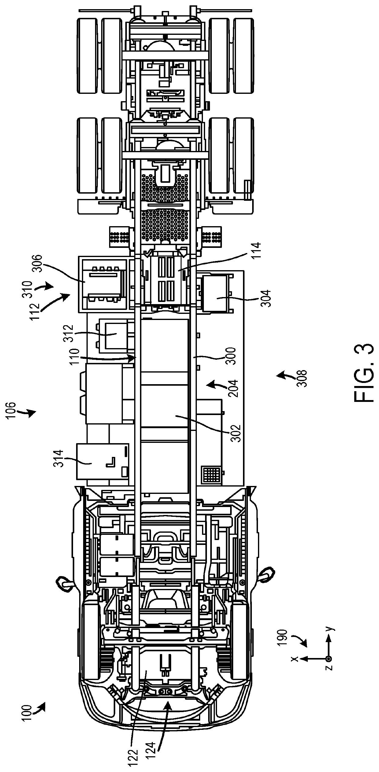
[0019]A fuel cell cooling arrangement and associated systems that achieve a higher level of cooling and efficiency in comparison to previous cooling systems are described herein. To achieve the high level of heat rejection and efficiency, the fuel cell cooling arrangement is positioned above a hydrogen fuel cell assembly that is positioned behind a vehicle cab. This fuel cell cooling arrangement includes an inlet manifold positioned vertically above the cab and in fluidic communication with a fan array that is designed to drive airflow to a fuel cell assembly heat exchanger. The cooling arrangement further includes a deflector with inlets that are designed to guide ram air, generated during vehicle travel, to the fan arrays. To form inlets, the deflector may include slats that extend across a front opening. The attack angle of the slats may be selected to strike a desired balance between airflow through the fuel cell cooling system and vehicle drag. Positioning the cooling component...


PUM

PropertyMeasurementUnit
angleaaaaaaaaaa
gross vehicle weight ratingaaaaaaaaaa
voltageaaaaaaaaaa

Abstract

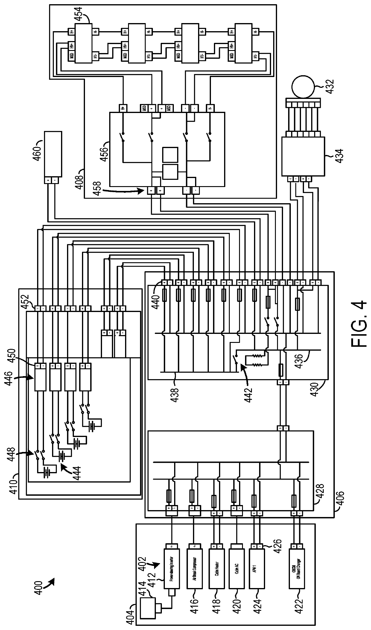
Methods and systems are provided for cooling a hydrogen fuel cell assembly. A vehicle system, in one example, includes a hydrogen fuel cell assembly electrically coupled to a traction motor, positioned behind a cab, and including a plurality of hydrogen storage tanks and hydrogen fuel cells. The vehicle system further includes a fuel cell cooling assembly including an inlet manifold in a deflector, where the deflector is fixedly coupled to and positioned vertically above the cab and designed to direct airflow to a fan array that is coupled to a fuel cell assembly heat exchanger, where the fan array is positioned behind inlet manifold and longitudinally offset therefrom.

Description

CROSS-REFERENCE TO RELATED APPLICATION[0001]The present application claims priority to U.S. Provisional Application No. 63 / 181,090, entitled “ELECTRIC POWERTRAIN AND METHOD FOR OPERATION OF SAID POWERTRAIN”, and filed on Apr. 28, 2021. The entire contents of the above-listed application are hereby incorporated by reference for all purposes.FIELD[0002]The present description relates generally to methods and systems for an electric powertrain with a fuel cell cooling assembly.BACKGROUND AND SUMMARY[0003]Electric powertrains have previous utilized either battery technology or fuel cells to provide electric energy for a traction motor. Both electric vehicle technologies do not generate hydrocarbon emissions during vehicle operation, which may provide an attractive alternative to vehicles with internal combustion engines when taking into account environmental factors during vehicle design.[0004]US 2021 / 0155224 A1 to McKibben et al. discloses a heavy duty vehicle with a power distribution...

Claims


Application Information

Patent Timeline
Patent Type & Authority Applications(United States)
IPC IPC(8): B60L58/33B60L58/40B60K11/06B60K1/04H01M8/04007
CPCB60L58/33B60L58/40B60K11/06B60K1/04H01M8/04007H01M2250/20B60L2240/36H01M50/244H01M50/249H01M10/425B60K2001/0438Y02T90/40Y02T10/70Y02E60/50Y02E60/10B60L1/003B60L15/2063B60L50/75B60L53/22B60L58/18B60L58/26B60L2210/10B60L2240/12B60L2240/54B60Y2200/14B60K1/00B60Y2400/202B60K2001/005B60K11/02B60K15/07B60Y2200/145H01M8/04303H01M2220/20H01M10/625H01M10/613H01M8/04626H01M16/006H01M10/48H01M8/0432H01M8/04302H01M8/04955B60K2001/0405B60R16/0238B60L58/30B60K2001/0494
Inventor DELRIEU, FREDERICKEIGHAN, MARTINLEMPERT, JEREMYHOULE, MARTIN
Owner DANA HEAVY VEHICLE SYSTEMS GROUP LLC
Learn More