Diamond tool

a technology of diamonds and tools, applied in the field of diamond tools, to achieve the effect of improving the detection resistan

Pending Publication Date: 2022-11-10
SUMITOMO ELECTRIC HARDMETAL CORP
View PDF0 Cites 0 Cited by
  • Summary
  • Abstract
  • Description
  • Claims
  • Application Information

AI Technical Summary

Benefits of technology

[0009]According to the present disclosure, a diamond tool ...

Problems solved by technology

However, for this kind of work material, a cutting oil (hereinafter also referred to as “coolant”) often cannot be used during the processing.
In th...

Method used


Image

  • Diamond tool

Examples


examples

[0063]Hereinafter, the present disclosure will be described in more detail with reference to examples, but the present disclosure is not limited thereto. In the following description, Samples 1 to 9 are examples, and Sample 10 is a comparative example.

Manufacture of Diamond Tool

Sample 1

First Step

[0064]To manufacture the turning insert specified by catalog number “NF-DNMA150408” (Sumitomo Electric Industries, Ltd.), a diamond sintered body (PCD) was prepared by using a conventionally known HTHP method (sintering at a pressure of 6 GPa and a temperature of 1500° C. for 15 minutes). The grain size (D50) of the diamond grains constituting this PCD was 10 μm.

Second Step

[0065]An isosceles triangle having a top angle of 55° (bottom side of 6.5 mm×5 mm height) was cut from the PCD by using a commercially available wire electric discharge machining machine. The shape of the turning insert included a rake face, a flank face, and a ridgeline where the rake face and the flank face intersected, ...


PUM


Abstract

A diamond tool includes a diamond at least on a cutting edge including one or two or more diamond grains including a diamond phase composed of a diamond crystal structure and a graphite phase composed of a graphite crystal structure. When a ratio Iπ*/Iσ* between an intensity of a π* peak derived from a π bond of carbon in the graphite phase and an intensity of a σ* peak derived from a σ bond of carbon in the graphite phase and a σ bond of carbon in the diamond phase is determined for the diamond grain by measuring an energy loss associated with excitation of K-shell electrons of carbon by electron energy loss spectroscopy, the ratio Iπ*/Iσ* of the diamond grain on a surface of the cutting edge is 0.1 to 2 and a ratio Iπ*/Iσ* of the diamond grain at a depth position of 0.5 μm from the surface of the cutting edge is 0.001 to 0.1.

Description

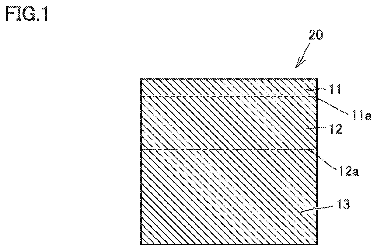
TECHNICAL FIELD[0001]The present disclosure relates to a diamond tool.BACKGROUND ART[0002]Conventionally, when processing work materials that are difficult to cut, for example, nonferrous metals such as aluminum alloys, carbon fiber reinforced plastics (CFRP), glass fiber reinforced plastics (GFRP), ceramics, ceramic matrix composites (CMC), and cemented carbides, diamond tools having a cutting edge that is substantially composed of diamond generally been used. However, for this kind of work material, a cutting oil (hereinafter also referred to as “coolant”) often cannot be used during the processing. In this case, the wear of the cutting edge becomes severe during machining, and therefore it is required to have improved wear resistance for the diamond tool.[0003]To meet this requirement, Japanese Patent Laid-Open No. 2005-088178 (PTL 1) discloses a diamond sintered body tool in which a graphite layer has been actively precipitated on a flank face by electric discharge machining. It...

Claims


Application Information

Patent Timeline
IPC IPC(8): B23B27/20B23C5/16
CPCB23B27/20B23C5/16B23B2226/315B23B27/14B23B51/00C23C16/27C23C16/32C23C30/005C23C28/044C23C28/347
Inventor HARADA, TAKASHIKUKINO, SATORUWATANOBE, NAOKI
Owner SUMITOMO ELECTRIC HARDMETAL CORP
Why Eureka
Try Eureka