Magnetic resonance system and transmission apparatus, transmission method, and pre-scanning method

a magnetic resonance and transmission apparatus technology, applied in the field of medical devices, can solve problems such as directivity errors, false triggering of sar protection, and measurement errors

Active Publication Date: 2022-11-17
GE PRECISION HEALTHCARE LLC
View PDF1 Cites 0 Cited by
  • Summary
  • Abstract
  • Description
  • Claims
  • Application Information

AI Technical Summary

Problems solved by technology

However, during measurement of the above indicators, an isolation degree of the coupler itself results in measurement errors, namely directivity errors.
For example, when the actual VSWR is 1.4, if a coupler having a directivity of 15 dB is used, then a measured VSWR is in the range of 1-2.1 and has a large error, and the error of a measured reverse power is 300% or more, thereby resulting in a large error also in an SAR calculated by means of the reverse power, and accordingly causing SAR protection to be falsely triggered.
However, even with a 20 dB directivity, the error of a measured reverse power is still 150% or more.
However, in the existing design methods, it is difficult to design a coupler having a directivity greater than 25-30 dB, especially for loose coupling in high radio-frequency power applications such as MR, etc.

Method used


Image

  • Magnetic resonance system and transmission apparatus, transmission method, and pre-scanning method
  • Magnetic resonance system and transmission apparatus, transmission method, and pre-scanning method
  • Magnetic resonance system and transmission apparatus, transmission method, and pre-scanning method

Examples


embodiments of first aspect

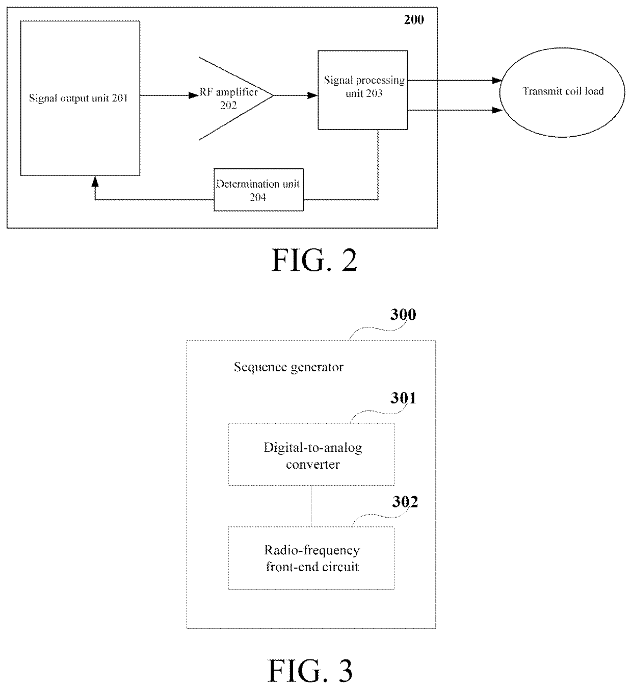
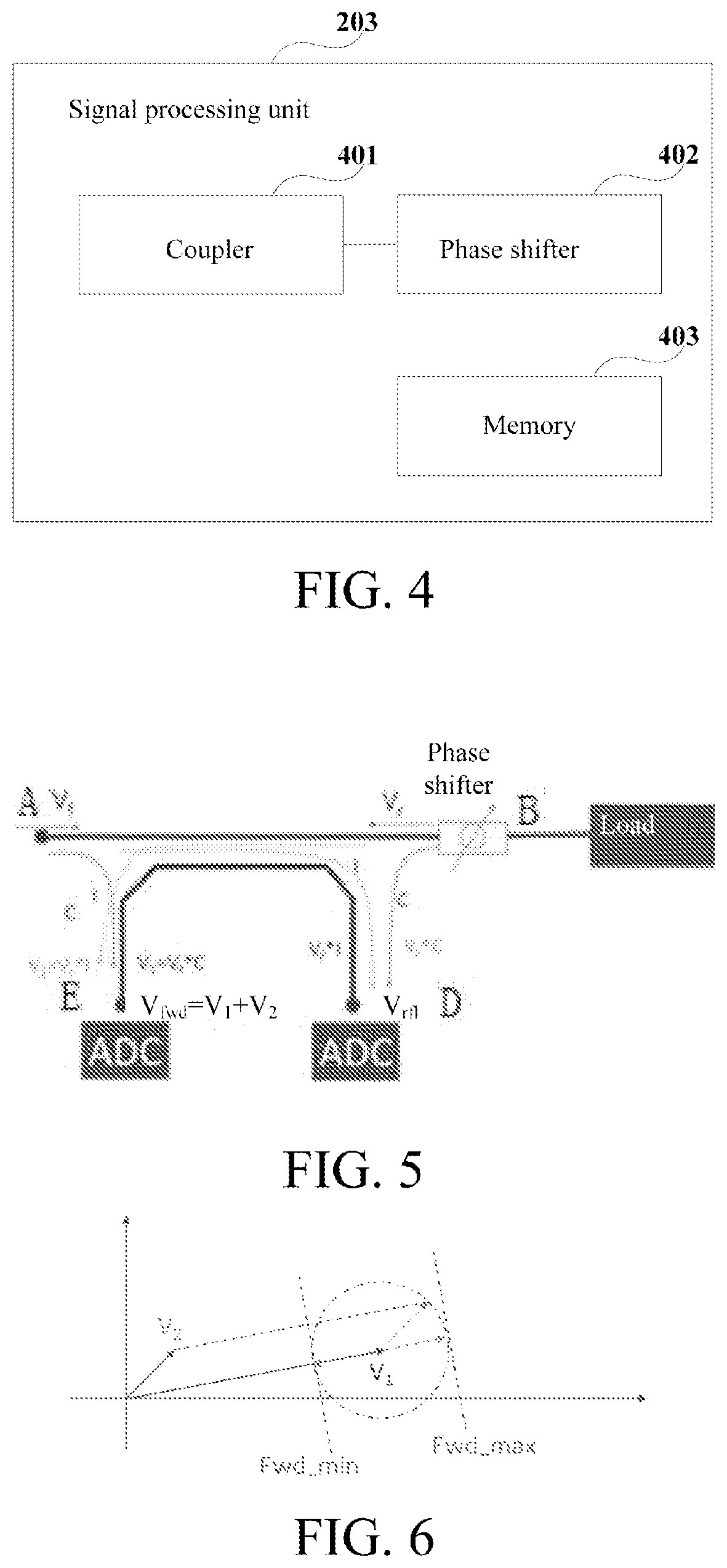
[0037]An embodiment of the present application provides a transmission apparatus of a magnetic resonance system. FIG. 2 is a schematic diagram of the transmission apparatus of the magnetic resonance system according to the embodiment of the present application. As shown in FIG. 2, the apparatus 200 includes a signal output unit 201 used to generate and output a pulse signal and a radio-frequency amplifier 202 used to amplify the pulse signal. The apparatus further includes a signal processing unit 203 used to transmit, to a transmit coil of the magnetic resonance system, the signal amplified by the radio-frequency amplifier 202, receive and adjust a phase of a feedback signal, and output the phase-adjusted feedback signal to the signal output unit. The apparatus also includes a determination unit 204 used to acquire amplitude values of the feedback signal at different phases, and determine a forward power and / or a reverse power according to the amplitude values of the feedback signa...

embodiments of second aspect

[0063]The embodiments of the present application provide a transmission method for a magnetic resonance system. The same content as that of the embodiments of the first aspect is not repeated herein.

[0064]FIG. 7 is a schematic diagram of the transmission method for the magnetic resonance system according to an embodiment of the present application. As shown in FIG. 7, the transmission method for the magnetic resonance system includes at step 701, a signal output unit generating and outputting a pulse signal and at step 702, a radio-frequency amplifier amplifying the pulse signal. The system further includes at step 703, a signal processing unit transmitting, to a transmit coil of the magnetic resonance system, the signal amplified by the radio-frequency amplifier, and outputting a phase-adjusted feedback signal to the signal output unit. The system also includes at step 704, the signal processing unit adjusting a phase of a feedback signal, and a determination unit acquiring amplitu...

embodiments of third aspect

[0073]The embodiments of the present application further provide a magnetic resonance imaging system.

[0074]FIG. 8 is a schematic diagram of components of the magnetic resonance imaging system. As shown in FIG. 8, the system 800 includes a transmit coil 801 and the transmission apparatus 200 according to the embodiments of the first aspect, and can be used to configure scanning parameters before the MRI system performs pre-scanning or formal scanning. The same content as that of the embodiments of the first aspect is not repeated herein.

[0075]In some embodiments, the magnetic resonance imaging system may further include a main magnet assembly 802, a gradient coil assembly 803, a gradient coil driver 804, a reception apparatus 805, a controller 806, a scanning table 807, an image processing unit 808, etc. For specific implementations, reference may be made to the related art, and the embodiments of the present application are not limited thereto.

[0076]In some implementations, the main...


PUM


Abstract

Embodiments of the present application provide a magnetic resonance system and a transmission apparatus, a transmission method, and a pre-scanning method. The apparatus includes: a signal output unit used to generate and output a pulse signal; a radio-frequency amplifier used to amplify the pulse signal; a signal processing unit used to transmit, to a transmit coil of the magnetic resonance system, the signal amplified by the radio-frequency amplifier, receive and adjust a phase of the feedback signal, and output the phase-adjusted feedback signal to the signal output unit; and a determination unit used to acquire amplitude values of the feedback signal at different phases, and determine a forward power and/or a reverse power according to the amplitude values of the feedback signal at the different phases.

Description

CROSS REFERENCE[0001]The present application claims priority and benefit of Chinese Patent Application No. 202110511876.2 filed on May 11, 2021, which is incorporated herein by reference in its entirety.FIELD OF THE INVENTION[0002]Embodiments of the present application relate to the technical field of medical devices, and relate in particular to a magnetic resonance system and a transmission apparatus, a transmission method, and a pre-scanning method.BACKGROUND OF THE INVENTION[0003]Magnetic resonance (MR) imaging systems are widely used in the field of medical diagnosis. A magnetic resonance system generally has a main magnet, a gradient radio-frequency amplifier, a gradient coil, a transmit chain module, a transmit / receive coil, a receive chain module, etc. The transmit chain module generates a pulse signal and transmits the same to the transmit / receive coil. The transmit / receive coil generates a radio-frequency excitation signal to excite a scanned object to generate a magnetic r...

Claims


Application Information

Patent Timeline
Patent Type & Authority Applications(United States)
IPC IPC(8): G01R33/36
CPCG01R33/3607G01R33/3614G01R33/36G01R33/32A61B5/055
Inventor LIU, YUXIE, XINSONG, TINGTINGWANG, KAIXING, HAOYANGYANG, DONGLIANGXIAO, CHUNLAINING, JIANYE
Owner GE PRECISION HEALTHCARE LLC
Why Eureka
Try Eureka