Method of making a printhead having reduced surface roughness

a technology of surface roughness and printhead, which is applied in the direction of vacuum evaporation coating, coating, inking apparatus, etc., can solve the problems of less energy and separation of bulging ink, and roughness of the underlying polysilicon, so as to improve the efficiency of drop ejection

Inactive Publication Date: 2000-01-11
XEROX CORP
View PDF7 Cites 28 Cited by
  • Summary
  • Abstract
  • Description
  • Claims
  • Application Information

AI Technical Summary

Benefits of technology

The invention relates generally to thermal ink jet printing and, more particularly, to printheads with resistive heaters provided with improved drop ejection efficiency.

Problems solved by technology

As the bubble begins to collapse, the ink still in the channel between the nozzle and bubble starts to move towards the collapsing bubble, causing a volumetric contraction of the ink at the nozzle and resulting in the separating of the bulging ink as a droplet.
Although these techniques do in fact result in vapor bubble nucleation with lower energy input, the drops ejected will be much less energetic and, hence, less efficient, than a drop generated by homogeneous vapor bubble nucleation, since the degree of superheating of the ink is lower.
However, in both of these example of prior art, diborides are used only as thermal energy generation layers (heater resistors), and any modification of the surface finish of the heater is provided only by the degree of smoothing of the substrate.
Therefore, the surface of the tantalum layer reproduces the surface side and hence, roughness of the underlying polysilicon and the nucleation efficiency of a heater structure of this type (polysilicon or ZrB.sub.2 with conventional dielectric passivation layer and tantalum) is not optimum.
These techniques are not entirely satisfactory because of the excessively high temperatures and / or long heating cycles, resulting in incompatibility with integrated microelectronics circuitry.
In addition, these techniques reduce the surface topography of the final heater surface simply by altering the topography of the initial substrate surface, and make no attempt to reduce the topography introduced by the resistive heater element and its' passivation stack, thus limting the degree of smoothness obtainable.

Method used


Image

  • Method of making a printhead having reduced surface roughness
  • Method of making a printhead having reduced surface roughness

Examples


Embodiment Construction

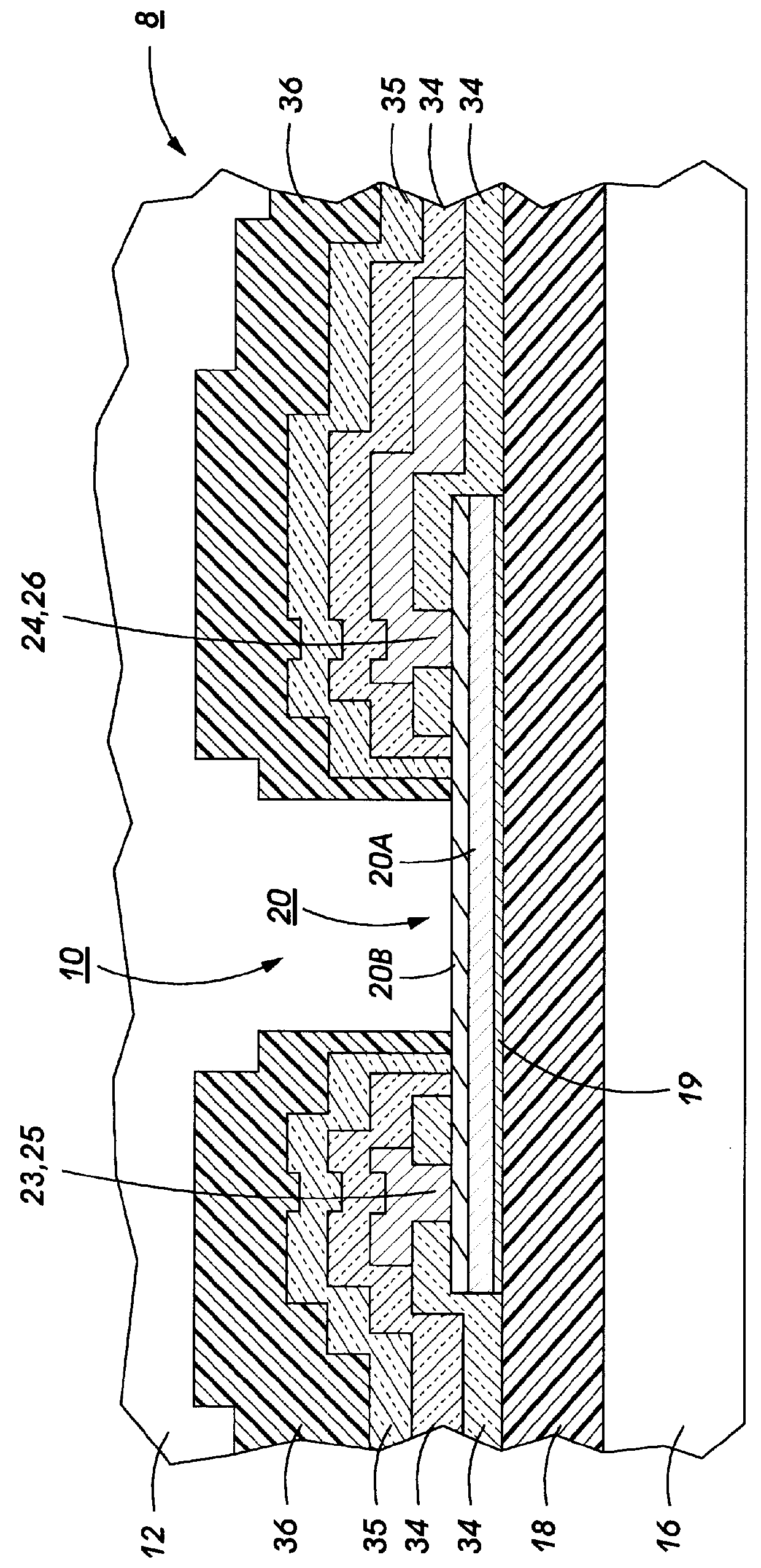
FIG. 1 is a cross-sectional view of a first embodiment of an improved resistive heater structure which can be used, for example, in a printhead of the type disclosed in U.S. Pat. Nos. Re. 32,572, 4,774,530 and 4,951,063, whose contents are hereby incorporated by reference. It is understood that the improved heater structures of the present invention can be used in other types of thermal ink jet printheads where a resistive element is heated to nucleate ink in an adjoining layer.

Referring to FIG. 1, the heater substrate portion of an ink jet printhead 8 is shown with ink in channel 10 being ejected from nozzle 12 formed in the front face. Printhead 8 is fabricated by a conventional process (except for the formation of the heater resistor) by bonding together channel and heater plates as disclosed in U.S. Pat. Nos. Re. 32,572 and 4,951,063, referenced supra. A silicon substrate 16 has an underglaze layer 18 formed on its surface. In one embodiment, it is a thermal field oxide. A gate ...


PUM

PropertyMeasurementUnit
surface roughnessaaaaaaaaaa

Abstract

The nucleation efficiency of a thermal ink jet printhead is improved by providing a heater resistor with a thin planar oxide film formed over a conductive heater resistive layer. In a preferred embodiment, zirconium diboride is sputtered onto a silicon substrate surface to form a first, electrically conductive base portion of the resistor. At a predetermined time, during the sputtering process, oxygen is introduced to form a thin film of ZrB2Ox. The surface of this film is very smooth having a surface roughness of <5 nm RMS.

Description

BACKGROUND OF THE INVENTION AND MATERIAL DISCLOSURE STATEMENTThe invention relates generally to thermal ink jet printing and, more particularly, to printheads with resistive heaters provided with improved drop ejection efficiency.Thermal ink jet printing is generally a drop-on-demand type of ink jet printing which uses thermal energy to produce a vapor bubble in an ink-filled channel that expels a droplet. A thermal energy generator or heating element, usually a resistor, is located in the channels near the nozzle a predetermined distance therefrom. An ink nucleation process is initiated by individually addressing resistors with short (2-6 .mu.second) electrical pulses to momentarily vaporize the ink and form a bubble which expels an ink droplet. As the bubble grows, the ink bulges from the nozzle and is contained by the surface tension of the ink as a meniscus. As the bubble begins to collapse, the ink still in the channel between the nozzle and bubble starts to move towards the co...

Claims


Application Information

Patent Timeline
Patent Type & Authority Patents(United States)
IPC IPC(8): B41J2/14B41J2/16B41J2/05
CPCB41J2/14129B41J2/1603B41J2/1626B41J2/1646B41J2202/03
Inventor RAISANEN, ALAN D.BURKE, CATHIE J.
Owner XEROX CORP
Why Eureka
Try Eureka