Chemical sensing techniques employing liquid-core optical fibers

a liquid-core optical fiber and chemical sensing technology, applied in the field of optical detection improvement, can solve the problems of limited sensitivity, severe limited life expectancy of sensors, and use of evanescent sensors

a liquid-core optical fiber and chemical sensing technology, applied in the field of optical detection improvement, can solve the problems of limited sensitivity, severe limited life expectancy of sensors, and use of evanescent sensors

US6016372AInactive Publication Date: 2000-01-18WORLD PRECISION INSTR

Image

  • Chemical sensing techniques employing liquid-core optical fibers
  • Chemical sensing techniques employing liquid-core optical fibers
  • Chemical sensing techniques employing liquid-core optical fibers

Examples


Embodiment Construction

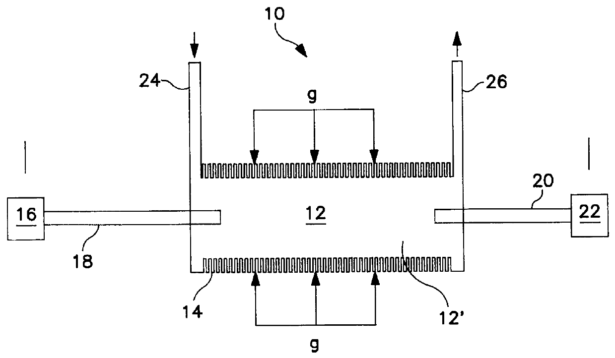
The present invention employs a liquid core waveguide as the main body, i.e., the probe, of a sensor. Referring to FIG. 1, a liquid core waveguide having properties which enable its use in the invention is indicated generally at 10. Waveguide 10 comprises a substantially optically transparent liquid core region 12 surrounded by a material, i.e., a tube 14, having a lower refractive index (relevant to the wavelength range of light used) than the liquid material 12' comprising the core. Light will propagate inside the waveguide with negligible losses due to the total internal reflection at the surface of the lower refractive index material provided that the launching angle of the light into the core is within the acceptance angle of the material comprising tube 14.

In practice as schematically illustrated in FIG. 1, the sensor probe is coupled to a light source 16 which illuminates the core liquid 12' via a solid optical fiber 18, or bundle of such fibers. Light exits the waveguide at ...


PUM

PropertyMeasurementUnit
refractive indexaaaaaaaaaa
thicknessaaaaaaaaaa
thickaaaaaaaaaa

Abstract

A gas or vapor permeable optical fiber waveguide with a liquid core is employed as a probe for the detection or measurement of a chemical specie of interest by filling the waveguide core region with a reagent liquid which undergoes a change in an optical characteristic thereof when exposed to the chemical specie and then inserting the filled waveguide into an environment in which the chemical specie may be present. The chemical specie, if present, will permeate through the waveguide wall and react with or be absorbed in the core liquid. Sensitivity is enhanced by controlling the pressure differential across the waveguide wall and / or by shaping the waveguide to enlarge the surface area. When the reaction generates light, the devices which detect that light will be shaped and disposed to maximize the collection thereof.

Description

1. Field of the InventionThis invention relates to improvements in the optical detection of different chemical species and, particularly, to enhancing the efficiency of techniques for identification and / or quantitative measurement of chemical substances of interest wherein changes in the optical properties of a reagent / solvent caused by the reaction with or dissolution of the said chemical substance in the reagent / solvent are detected. More specifically, the present invention is directed to devices for use in optically detecting the presence and / or concentration of species which are in the gas or vapor phase or are dissolved in a liquid matrix and, especially, to apparatus which enables the sensing of changes in the optical properties of a confined light conducting medium resulting from exposure of the confining vessel to the sample matrix of interest. Accordingly, the general objects of the present invention are to provide novel and improved techniques and apparatus of such charact...

Claims


Application Information

Patent Timeline
18 Jan 2000
Publication
US6016372A
IPC
G01N21/03; G01N21/77; G01N21/05; G02B6/02; G02B6/032
CPC
G01N21/05; G01N21/7703; G02B6/032; G01N21/80
Inventors
FEIN, HARRY; LIU, SU-YI