Laser-intervening micro-electrochemical machining method and device

A technology of micro-electrolysis and processing methods, which is applied in the field of micro-electrolytic machining, can solve the problems of limiting the ratio of depth to diameter of micro-electrolytic machining, the bottom of the processing area has protrusions, and low processing efficiency, so as to achieve high-efficiency processing, low taper, and improved The effect of processing efficiency

Active Publication Date: 2018-05-01
NINGBO INST OF MATERIALS TECH & ENG CHINESE ACADEMY OF SCI
View PDF9 Cites 24 Cited by
  • Summary
  • Abstract
  • Description
  • Claims
  • Application Information

AI Technical Summary

Problems solved by technology

Using the side insulation method of the tool electrode can effectively improve the precision of micro-electrolytic machining, but there are still problems such as low machining efficiency and protrusions at the bottom of the machining area.
In addition, there are problems such as difficult liquid supply and low processing efficiency in the deep processing area when micro-electrolytic machining of microstructures with large depth-to-diameter ratios, which limits the improvement of micro-electrolytic machining depth-to-diameter ratios

Method used


Image

  • Laser-intervening micro-electrochemical machining method and device
  • Laser-intervening micro-electrochemical machining method and device
  • Laser-intervening micro-electrochemical machining method and device

Examples


Embodiment 1

[0093] Example 1 Laser Interventional Micro Electrolytic Machining

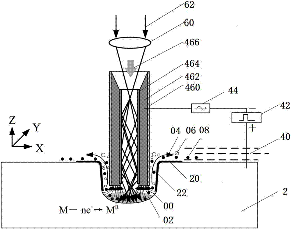
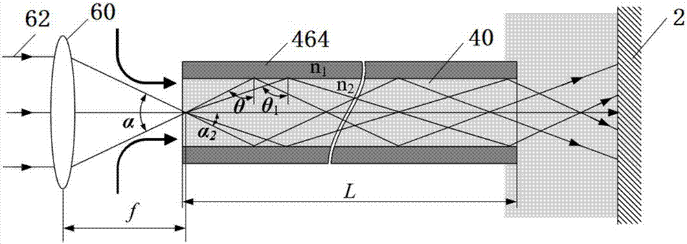
[0094] In this embodiment, micro-electrolytic machining is performed based on the laser photothermal effect, and the schematic diagrams involved are as follows figure 1 shown. Specifically include the following steps:

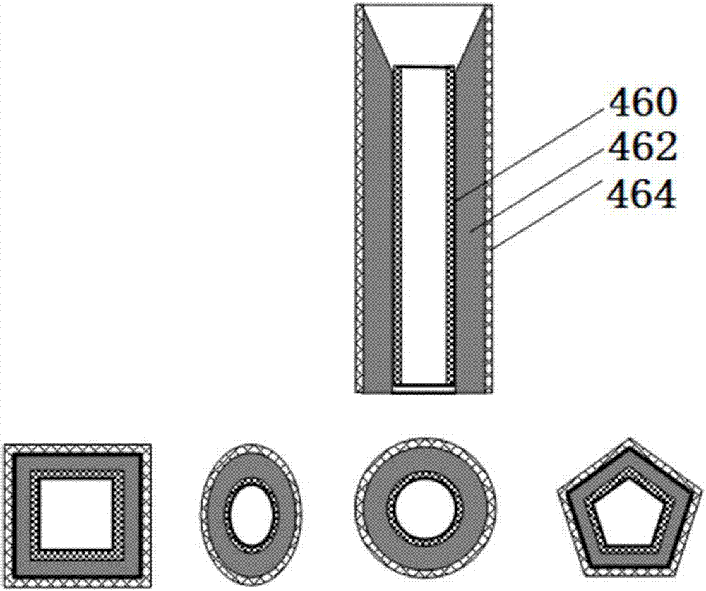
[0095] (1) installing the liquid-core optical fiber 464 in a side-insulated metal conduit 462 to form a tool electrode; the liquid-core optical fiber is coaxially located in the metal conduit;

[0096] (2) Clamp the tool electrode above the workpiece 2, and reasonably set the initial machining gap between the end of the tool electrode and the machining surface of the workpiece to be about 0.2 mm;

[0097] (3) The electrolyte 40 flows into the coupling system between the laser and the liquid-core optical fiber, and then flows into the liquid-core optical fiber 464 in the tool electrode to be transmitted to the processing area;

[0098] (4) adjust the laser beam 62 to pass through the focusin...

Embodiment 2

[0109] Example 2 Laser Interventional Micro Electrolytic Machining

[0110] The difference between laser-intervened micro-electrolytic machining in this embodiment and that in Embodiment 1 is:

[0111] (3) The electrolyte 40 flows into the coupling system of the laser and the liquid core fiber through the electrolyte through a high-pressure metering pump and a precision filter system, and flows into the liquid core fiber 464 in the tool electrode at a certain pressure and flow rate to be transported to the processing area.

[0112] The voltage amplitude between the tool electrode and the workpiece to be processed is 15V, and the frequency is 100KHz.

[0113] The electrolyte is a 0.05mol / L sodium nitrate solution with a flow rate of 0.01m 3 / h.

[0114] All the other operations are the same as in Example 1.

Embodiment 3

[0115] Example 3 Laser Interventional Micro Electrolytic Machining

[0116] The difference between laser-intervened micro-electrolytic machining in this embodiment and that in Embodiment 1 is:

[0117] (3) Electrolyte 40 flows into the laser and liquid core optical fiber coupling system through the electrolyte through the high pressure metering pump and precision filter system, and flows into the liquid core optical fiber 464 in the tool electrode at a certain pressure and flow rate to be transmitted to the processing area;

[0118] The pressure of the electrolyte is 0.1-0.5MPa;

[0119] (6) The tool electrode is fed to the workpiece 2 at a certain feed rate, and the tool electrode based on the liquid core optical fiber 464 can deeply intervene in the deep processing area of ​​the workpiece 2 to obtain a fine structure with a large aspect ratio. The voltage amplitude between the tool electrode and the workpiece to be processed is 15V, and the frequency is 30KHz.

[0120] Whe...


PUM

PropertyMeasurementUnit
refractive indexaaaaaaaaaa

Abstract

The invention discloses a laser-intervening micro-electrochemical machining method. The laser-intervening micro-electrochemical machining method comprises at least the following steps that a tool electrode and a to-be-machined workpiece are connected with a negative electrode and a positive electrode of a power supply correspondingly; lasers and an electrolyte are transmitted through the tool electrode to a machining area of the to-be-machined workpiece; and after the power supply is switched on, micro-electrochemical machining is conducted, the tool electrode is fed towards the to-be-machinedworkpiece, and a target structure is obtained. In the laser-intervening micro-electrochemical machining method and a laser-intervening micro-electrochemical machining device, laser beams are transmitted through liquid core optical fibers to the deep machining area in a full reflection mode, large-depth coupling of a laser energy field and electrochemical machining is achieved, and efficient machining of a micro-structure with the large depth-diameter ratio can be achieved.

Description

technical field [0001] The application relates to a laser-intervened micro-electrolytic machining method and a device thereof, which belong to the field of micro-electrolytic machining. Background technique [0002] With the development of science and technology, microstructures with large depth-to-diameter ratio have been widely used in aerospace, precision molds, micro-electromechanical systems (MEMS), precision medicine, weaponry and other fields. Micro-electrolytic machining removes workpiece material in the form of ions. It has the advantages of good surface integrity, wide variety of processed materials, and no loss of tool negative electrodes. It shows broad application prospects in the field of micro-machining. [0003] Micro-electrolytic machining is based on the principle of electrochemical anodic dissolution to remove workpiece materials. By controlling the area affected by electrolytic etching to control the removal accuracy of materials, the processing of micro-...

Claims


Application Information

Patent Timeline
Patent Type & Authority Applications(China)
IPC IPC(8): B23H7/38B23H9/14
CPCB23H7/38B23H9/14
Inventor 张文武王玉峰
Owner NINGBO INST OF MATERIALS TECH & ENG CHINESE ACADEMY OF SCI
Why Eureka
Try Eureka