Ozone generator control system

Inactive Publication Date: 2000-02-01
DUNDER OVE KARL
6 Cites 26 Cited by

AI-Extracted Technical Summary

Problems solved by technology

Variacs have the disadvantage that they need to be adjusted by mechanical means.
It is however not possible to vary the phase angle to the gate of such triacs in small increments in an accurate manner.
The disadvantage is that the control is only effective over a limited frequency range because of the inherent characteristics of the high voltage transformer.
The noise from the high voltage ozone generation means therefore interferes with the reliable operation of the control means.
This is a disadvantage when electronic controls are use.
(b) When triacs and silicon controlled rectifiers are used to regulate the amount of ozone used in the ozo...

Method used

The ozone production can be accurately controlled over a range of 8% to 100% of capacity by adjusting the output voltage from voltage regulator 3 at a constant frequency of output pulses from pulse generator 4. The resistor network 8 in the preferred embodiment has 5 resistors with different resistance values. For a selection of resistance values of the resistors in resistor network 8 such t...

Benefits of technology

The ozone production can be accurately controlled over a wide range by adjusting the regulated output vol...

Abstract

An ozone generator control circuit comprising corona discharge, circuitry to electrically control a regulator voltage applied to a pulse generating device for a corona discharge; circuitry to electrically control the frequency of the pulses applied to the pulse generator for the corona discharge. The electrical control circuit is optically isolated from the pulse generating circuit.

Application Domain

Analysis by electrical excitationElectrical discharge ozone preparation +1

Technology Topic

Electrical controlCorona discharge +5

Image

  • Ozone generator control system

Examples

  • Experimental program(1)

Example

. 1
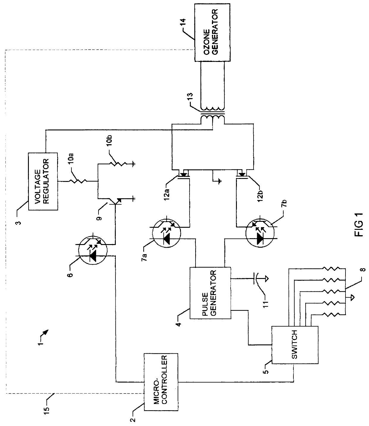
The ozone generator control system 1 illustrated comprises a microcontroller 2, a pulse generator 4, a switch 5, a voltage regulator 3, a transformer 13, an ozone generator 14, and electronic components 6, 7a, 7b, 8, 9, 10a, 10b, 11, 12a, 12b.
The microcontroller 2 has two control line outputs and one sensor input. One line controls the selection of a resistor from resistor network 8 and the other line controls the analog voltage level applied to optoisolator 6. The input line 15 from the ozone sensor monitors the ozone concentration in ozone generator 14.
The pulse generator 4 generates a complementary square wave output to optoisolators 7a and 7b. The frequency of the square wave is controlled by the RC time constant of capacitor 11 and the selected resistor in resistor network 8.
The voltage regulator 3 supplies a regulated voltage to the center tap of transformer 13. In the preferred embodiment as shown in FIG. 1 the range of the regulated voltage is 65 to 120 VDC. However the regulated voltage range can have other values, the silent corona discharge gap and the transformer design being two of the design parameters. The regulated voltage level is controlled with transistor 9. The conductance of transistor 9 depends on the supply current to its base from optocoupler 6.
The optoisolators described herein can be described as an optical coupler which can consist of an LED input optically coupled to a photocell. The photocell resistance of optoisolators 7a and 7b is high when the LED current is "off" and low resistance when the LED current is "on". In optocoupler 6 the photo transistor produces an output signal that varies linearly with the LED current.
The transformer 13 is supplied with regulated voltage to its center tapped primary winding from voltage regulator 3. The primary winding is connected to two MOSFETS 12a and 12b in a push-pull power amplifier configuration. The gates of the MOSFETS are controlled by optoisolators 7a and 7b. Other power amplifier configuration can be used with the invention to achieve similar results.
The ozone generator 14 receives high voltage pulses from transformer 13. The intensity of the silent corona discharge inside the ozone generator is proportional to the amplitude and frequency of the high voltage pulses.
From the description above, a number of advantages of the ozone generator control system are observed:
(a) The ozone generator control system uses only electronic means for the control of the production of ozone in the ozone generator.
(b) The ozone generator control system adjusts the amount of ozone produced accurately in small increments.
(c) The ozone generator control system adjusts the amount of ozone produced accurately over the full range of ozone production.
(d) The ozone generator control system is electrically isolated from the noise interference from the high voltage ozone generation means, by means of optoisolators 6, 7a and 7b.
The circuitry described herein and particularly the microcontroller 2 which controls the frequency levels of the applied pulses, can regulate the voltage levels according to a difference signal between a sensor sensing ozone concentrations in the ozone generator 17 and a preset required level.
Operation--FIG. 1
The microcontroller 2 controls the ozone production with two output lines. One line conducts an analog signal which is coupled through an optocoupler 6 to the base of the transistor 9. Transistor 9 is connected in parallel with resistor 10b and will bypass resistor 10b more or less in proportion to the analog drive signal from the microcontroller 2 resulting in a varied resistance seen by voltage regulator 3 through resistor 10a. The regulated voltage output from voltage regulator 3 is directly proportional to the resistance seen through resistor 10a.
The regulated voltage from voltage regulator 3 is connected to the center tap of transformer 13. The peak voltage of the pulses in the primary of transformer 13 therefore equals the regulated voltage. In the preferred embodiment, as shown in FIG. 1, the peak of voltage of the pulses are stepped up from a range of 65 to 120 V to a range of 3,000 to 6,000 V and applied to ozone generator 14. The intensity of the silent corona discharge in ozone generator 14 is proportional to the amplitude of the applied pulses. The ozone production is proportional to the intensity of the silent corona discharge and it is consequently proportional to amplitude of the applied pulses.
The other line from microcontroller 2 conducts digital control signals that controls switch 5, which selects one of the resistors in resistor network 8. Pulse generator 4 has an internal oscillator with a frequency set by the RC time constant of capacitor 11 and the selected resistor in network 8. The frequency of the complementary square wave output from pulse generator 4 is therefore controlled by the value of the selected resistor in network 8. The square wave output from pulse generator 4 is applied to the gates of metal oxide semiconductor field effect transistors (MOSFET) 12a and 12b through optoisolators 7a and 7b. The MOSFETs 12a and 12b forms a push-pull power supply circuit which generates a square wave in the primary winding of transformer 13 and the secondary winding of transformer 13 is applied to ozone generator 14. The intensity of the silent corona discharge in ozone generator 14 is directly proportional to the frequency of the applied pulses. The ozone production is proportional to the intensity of the silent corona discharge and it is consequently directly proportional to frequency of the applied pulses.
Noise from the high voltage circuit is isolated from the low voltage control circuit through optoisolators 7a and 7b and optocoupler 6.
Input line 15 from an appropriate ozone sensor associated with ozone generator 14 monitors the ozone concentration and is used to control the frequency and regulated voltage applied to ozone generator 14.
The ozone production can be accurately controlled over a range of 8% to 100% of capacity by adjusting the output voltage from voltage regulator 3 at a constant frequency of output pulses from pulse generator 4. The resistor network 8 in the preferred embodiment has 5 resistors with different resistance values. For a selection of resistance values of the resistors in resistor network 8 such that the frequency of the output pulses in pulse generator 4 is set at 100 Hz for the highest resistor value and increases with 100 Hz for each selection of a resistor with a lower resistance value; the range of the ozone production is increased by a factor of 5 at the low end to 1.6% to 100%. The range of resistors in the resistor network can be increased for an even greater range of control.
Although the preferred embodiment as well as the operation and use have been specifically described in relation to the drawings, it should be understood that variations in the preferred embodiment could be achieved by a person skilled in the trade without departing from the spirit of the invention as claimed herein.

PUM

no PUM

Description & Claims & Application Information

We can also present the details of the Description, Claims and Application information to help users get a comprehensive understanding of the technical details of the patent, such as background art, summary of invention, brief description of drawings, description of embodiments, and other original content. On the other hand, users can also determine the specific scope of protection of the technology through the list of claims; as well as understand the changes in the life cycle of the technology with the presentation of the patent timeline. Login to view more.

Similar technology patents

Motor controller system for large dynamic range of motor operation

InactiveUS7081730B1Accurately controlFast rate of rotationTemperatue controlAnti-hunting elementsLarge dynamic rangeMotor drive
Owner:AERONAUTICS & SPACE ADMINISTATION UNITED STATES OF AMERICA AS REPRESENTED BY THE ADMINISTATOR OF THE NAT +1

Inkjet recording apparatus

InactiveUS20050259126A1Simple and inexpensive configurationAccurately controlPrintingEngineeringElectrical and Electronics engineering
Owner:CANON KK

Classification and recommendation of technical efficacy words

Why Eureka
Try Eureka