Method of making an antifogging window plate of synthetic resins

a technology of synthetic resins and window plates, applied in the direction of synthetic resin layered products, moulds, vehicle components, etc., can solve the problems of not only spoiling the appearance but also distorting the image seen through the window plate, and reducing the number of steps, so as to reduce the number of steps carried out

Inactive Publication Date: 2000-02-15
TSUTSUNAKA PLASTIC IND
View PDF22 Cites 67 Cited by
  • Summary
  • Abstract
  • Description
  • Claims
  • Application Information

AI Technical Summary

Benefits of technology

In the other mode, the contact members 11 are held tightly on the electrode's terminal portions 10 of the film 2 placed on the wall 7a of cavity, when the molten resin is injected thereinto. The resin solidifying to form the base 9 laminated with the film will perm...

Problems solved by technology

On the other hand, the problem of an atmospheric vapor condensing to fog the windows and to lower the visibility thereof has been reported, whether the windows are made of glass or plastics.
Such an undulation will not only ...

Method used


Image

  • Method of making an antifogging window plate of synthetic resins
  • Method of making an antifogging window plate of synthetic resins
  • Method of making an antifogging window plate of synthetic resins

Examples


first embodiment

[First Embodiment]

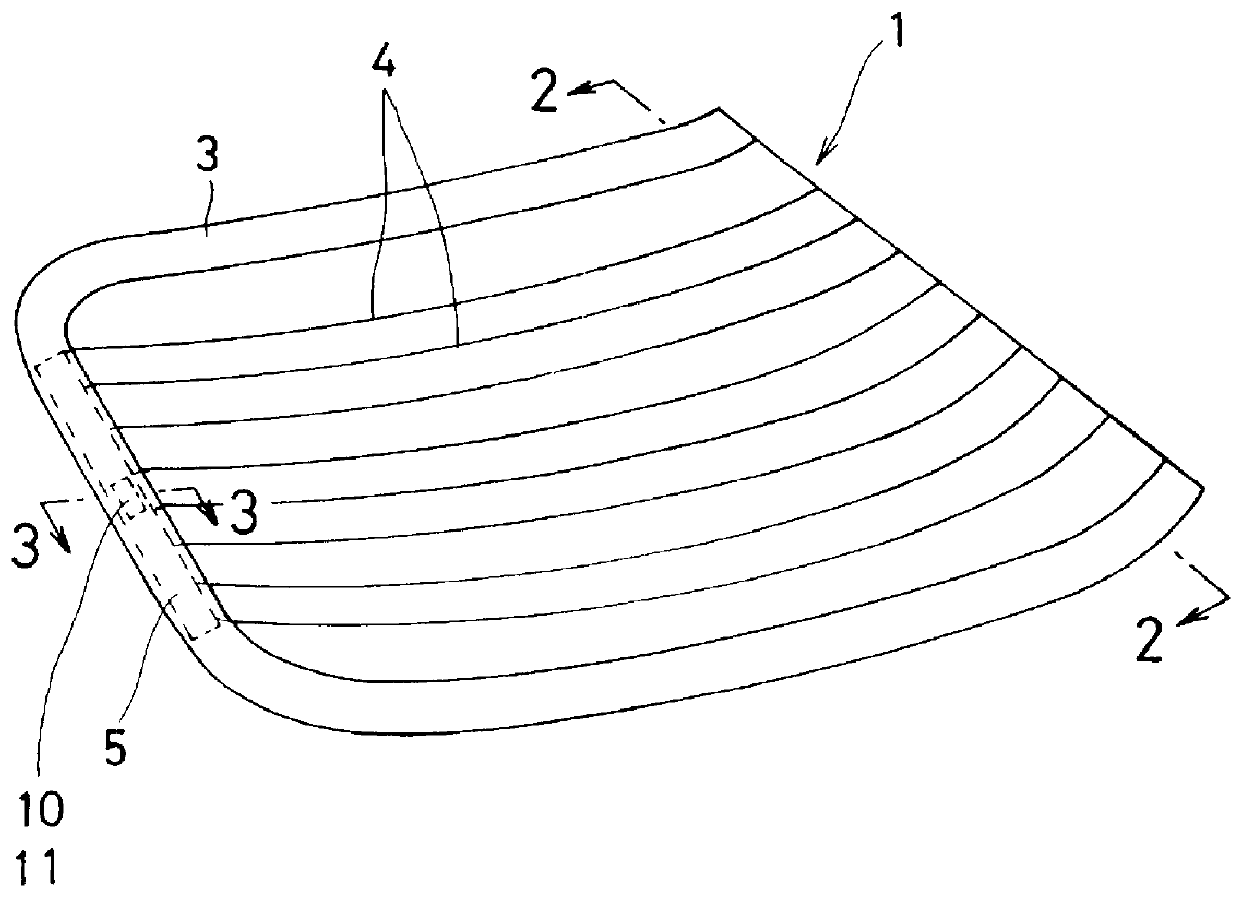
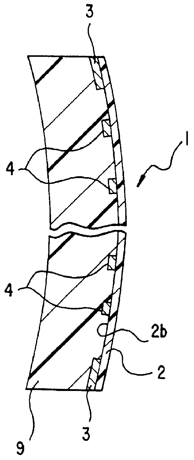
A plastics window plate 1 as shown in FIGS. 1 to 3 was produced for use as the automobile car's rear window.

This window plate was manufactured in the following manner.

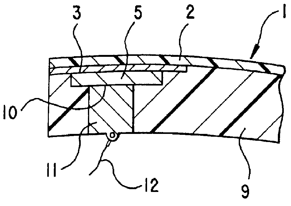
At first, a peripheral mask 3 of a width of 40 mm was printed using an opaque ink, to the peripheral zones of the transparent film 2 to define a contour of the rear window, as shown in FIG. 4. Subsequently, the conductive paste was screen-printed on the same side of said film. A plurality of conductive lines 4 thus formed at a pitch of 15 mm were 1.0 mm wide. A pair of electrodes 5 each 20 mm wide were printed on the mask 3 so as to be integral with the right and left ends of those lines 4. Then, the film 2 was heated in a far infrared oven at 120.degree. C. for 30 minutes to cure the printed lines and electrodes. A peripheral edge outside the mask 3 were punched off the film 2 to provide a finished film of a flat shape corresponding to the window plate which was to be produced.

At the next step shown ...

second embodiment

[Second Embodiment]

In the second embodiment, a window plate 1 of the same shape as that provided in the first embodiment, but installment of electric contact elements 11 was effected simultaneously with injection molding. FIG. 7 shows that the mold 6' used in this case is also of the same shape as that 6 in the first embodiment, except for the lugs 8 protruding into cavity 7 for defining terminal portions 10 on the electrodes 5. Thus, the same reference numerals are allotted to the members or elements in FIG. 7 that are the same as those shown in FIG. 5, and description thereof is abbreviated.

The mask was likewise printed with an opaque ink on the transparent film 2, which was then subjected to the screen-printing of the conductive paste. This film was then placed in the mold 6' and sucked such that its side 2a not printed did stick to the concave wall 7a of said mold. The contact elements 11 were thus held on the electrodes' terminal portions 10, before the mold 6' was closed. A mo...


PUM

PropertyMeasurementUnit
Thicknessaaaaaaaaaa
Timeaaaaaaaaaa
Thicknessaaaaaaaaaa

Abstract

An antifogging window plate has a transparent film and a base both made of thermoplastic resins. Conductive lines and electrodes are printed using a conductive paste on one side of the film, which is then bonded to the base. One portion of each electrode is exposed as a terminal portion to be connected to an electric contact member. The window plate is made by injection molding with the surface of the film opposite from the printed surface being in contact with the cavity wall of the mold, so that the integration of the film with the base is effected simultaneously with the forming of base. Each contact member is subsequently fitted in an injection-molded void facing the terminal portion, or is secured in place at the same time as the injection molding.

Description

1. Field of the InventionThe present invention relates to a window plate made of synthetic resins and adapted for use in the automobile vehicles or the like, and more particularly relates to a window plate made of synthetic resins to have an antifogging property, as well as a method of making the window plate.2. Prior ArtMany proposals have been made to substitute plastics boards for the classical glass windows, so as to render the automobile bodies lighter in weight. On the other hand, the problem of an atmospheric vapor condensing to fog the windows and to lower the visibility thereof has been reported, whether the windows are made of glass or plastics. Certain plastics window plates of a double-stratified structure consisting of a plastics base and a resin film bonded thereto were developed to resolve this problem. In connection with the plastic window, a pattern of electrically conductive heating wire has been proposed to be previously printed on the resin film.An example of suc...

Claims


Application Information

Patent Timeline
IPC IPC(8): B29C45/14B32B17/06B32B17/10B29C70/00B32B27/08B29C70/76H05B3/84H05B3/86B60S1/58B29C69/00B29D99/00B29K105/20B29L9/00B29L31/30
CPCB29C45/14778B29C45/14811B29C70/763B32B17/10376B32B27/08H05B3/86B29K2995/0005B29K2995/0026B29L2031/3052H05B2203/017B32B27/286B32B27/308B32B27/365B32B2255/10B32B2255/205B32B2307/412B32B2605/006
Inventor NANRI, HIROYOSHI
Owner TSUTSUNAKA PLASTIC IND
Why Eureka
Try Eureka