Optical recording medium and method for recording optical information

a technology of optical information and optical recording medium, which is applied in the field of optical recording medium and method for recording optical information, can solve the problems of loss of original characteristics of the layer, loss of signal, and difficulty in reproducing on the device such as the aforementioned cd-rom driv

Inactive Publication Date: 2000-03-07
KAO CORP
View PDF7 Cites 103 Cited by
  • Summary
  • Abstract
  • Description
  • Claims
  • Application Information

AI Technical Summary

Problems solved by technology

On the other hand, recently proposed write once type optical disks which employ inorganic materials in the recording layer (hereafter these disks are referred to as inorganic based optical disks) have relatively low reflectances, and reproduction on devices such as the aforementioned CD-ROM drives can be difficult.
Firstly, exposure of organic color based optical disks over long periods to even relatively weak light sources which exist in typical daily environments such as sunlight or electric lights, can cause photodecomposition of the organic color used in the recording layer, leading to a loss in the original characteristics of the layer.
Consequently, for example, if an organic color based optical disk on which a signal is recorded is left sitting in the sunlight the signal recorded on the disk will deteriorate, and may lead to a loss of the signal.
In addition, because the optical properties (such as the refractive index and the absorption coefficient) of the organic color varies greatly depending on the wavelength of the light, there is no compatibility with respect to wavelength.
That is, an organic color based optical disk designed with a reflectance and absorption value relative to the wavelength of a specific light source, will have greatly different reflectance and absorption values relative to another light source with a different wavelength, and so recording on, and or reproduction of the disk using a drive in which the wavelength of the light source is different from the original design may be impossible.
Furthermore, organic colors are typically low in rigidity, thus lowering the overall physical strength of the optical disk.
Of these various types, recording layers using the pitting technique (1) make wide use of Te based materials, where a large change in reflectance (degree of modulation) is observed between the situation before recording and that after recording, but these types of layers suffer from not having a very high reflectance prior to recording.
A further problem arises in that pits are easily formed in the surface, and so the recording layer needs to be protected with a complex construction known as an air sandwich.
For recording layers utilizing gas bubble formation within the layer (2) a problem arises that if the recording power is too high the bubbles can burst.
Examples of recording layers which utilize reaction within the layer (3) include double layered films of Bi and Se, and various configurations have been proposed, including those presented in Japanese Unexamined Patent Publication No. 56-8293, Japanese Unexamined Patent Publication No. 57-22095, Japanese Unexamined Utility Model Publication No. 4-89374, and Japanese Unexamined Patent Publication No. 6-131693, but the problem with these configurations is that they do not have a high enough reflectance prior to recording to allow reproduction compatibility on devices such as CD-ROM drives.
Furthermore, practical examples of recording layers utilizing phase change (4) include materials such as Ge-Sb-Te and Ag-In-Sb-Te, but none of the materials were able to provide the combination of a high reflectance prior to recording and a high degree of modulation.
In contrast, if the depth d of the guide track G is equal to or less than the lower limit of 0.03 / n mentioned above, then the difference in phase between light reflected from the guide track G and that reflected from the land will be small and result in very little interference effect, making it difficult to obtain both the push-pull signal used for tracking servo purposes, and the radial contrast signal.
If the width w of the guide track G is equal to or less than the lower limit of 0.1 P mentioned above then the amplitude of the push-pull signal used for tracking servo purposes decreases leading to the possibility of tracking errors.
The thicker the first recording layer 3 is the higher the reflectance prior to recording will be, but at thicknesses exceeding 50 nm the reflectance becomes almost saturated, and as the thickness of the layer increases the heating effect of the light beam becomes insufficient, resulting in a reduction in the recording sensitivity and signal quality.
If the thickness of the second recording layer 4 is less than 5 nm then the reflectance does not fall much following recording, resulting in an unsatisfactory degree of modulation.
Furthermore, if the thickness exceeds 200 nm the heating effect of the light beam becomes insufficient creating the possibility of a reduction in the recording sensitivity.
At thicknesses exceeding these values a lowering in the recording sensitivity and deterioration in the signal quality can result.
For layers of less than 5 nm thickness, formation of a uniform layer is difficult.
At thicknesses less than 10 nm the reflectance of the layer is insufficient.

Method used


Image

  • Optical recording medium and method for recording optical information
  • Optical recording medium and method for recording optical information
  • Optical recording medium and method for recording optical information

Examples


working example 1

(Working Example 1)

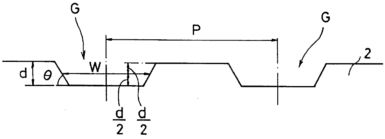
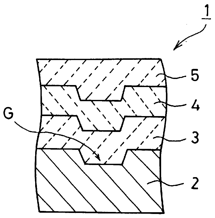
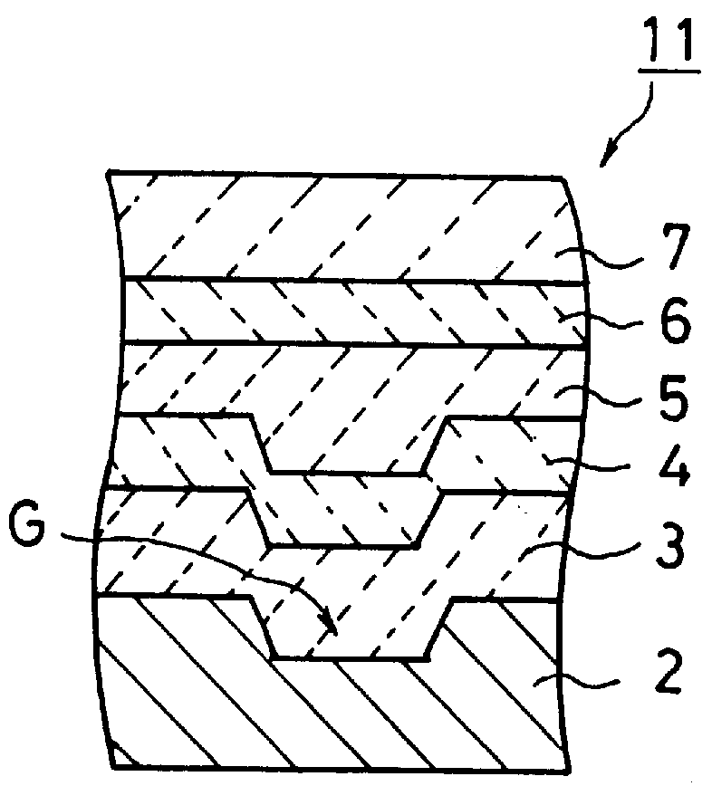
An optical recording medium 1 was constructed by forming on a transparent polycarbonate substrate 2 (diameter 12 cm, thickness 1.2 mm) incorporating a helical guide track (track pitch 1.6 .mu.m, track width approximately 0.7 .mu.m, track depth approximately 30 nm) a first recording layer 3 of 10 nm In using sputtering techniques, and following exposure to the atmosphere then forming a second recording layer 4 of 15 nm Te on top of the first recording layer 3 using sputtering techniques. A UV curing resin layer of approximately 10 .mu.m was then applied to the top of the second recording layer 4 using spin coat techniques, and this layer then cured by means of exposure to UV radiation, thus forming a protective layer 5 and completing the construction of the optical recording medium 1.

Next, using a CD-R evaluation apparatus, the optical recording medium 1 was spun at such a rate to generate a relative speed between the light spot and the medium of 1.2 m / s, and then ...

working examples 2

(about.7)

Optical recording media were constructed in the same manner as that described for the working example 1 with variations made in the thickness of, and material used in the first and second recording layers 3,4, and the media were then subjected to the same measurements as those described for the working example 1.

working examples 8

(about.23 and Comparative Examples 6.about.10)

Using transparent polycarbonate substrates 2 (diameter 12 cm, thickness 1.2 mm, track pitch 1.6 .mu.m) incorporating a helical guide track (track width approximately 0.5 .mu.m, track depth approximately 60 nm) a series of optical recording media were constructed in the same manner as the working example 1, with the exception that variations were made in the thickness of, and material used in the first and second recording layers 3, 4, and the media were then subjected to the same measurements as those described for the working example 1.


PUM

PropertyMeasurementUnit
reflectanceaaaaaaaaaa
diameteraaaaaaaaaa

Abstract

The present invention provides an optical recording medium which incorporates an inorganic based recording layer which has a high reflectance, sufficient for reproduction compatibility on devices such as CD-ROM drives, as well as a high degree of modulation between the state prior to recording and that after recording, as well as an information recording method therefor. Accordingly, an optical recording medium comprises a substrate (2) which is substantially transparent with respect to a recording light beam and a reproduction light beam, a first recording layer (3) which is layered on top of the substrate (2) and which incorporates as the main constituent a metal which has a low melting point and a high reflectance, and a second recording layer (4) which is layered on top of the first recording layer (3) and which will, due to heat generated from irradiation of a light beam through the substrate (2), either mix, or alternatively react, with the first recording layer (3) to form an alloy of low reflectance as well as forming irregularities or pitting in the surface, thereby enabling the recording of information. Due to the heat generated from irradiation of a recording light beam through the substrate (2) the first recording layer (3) and the second recording layer (4) are either mixed, or alternatively reacted to form an alloy as well as forming irregularities or pitting in the surface, thereby recording information.

Description

The present invention relates to an optical recording medium and a method for recording optical information, and in particular to a write once type optical recording medium comprising a recording layer of an inorganic material, on which information can only be recorded once, and a method for recording optical information.RELATED ART OF THE INVENTIONThe materials used for the recording layer of currently available write once type optical disks, that is, optical recording media on which information can only be recorded once, can be broadly divided into two groups; organic color based materials and inorganic materials. Of these, write once type optical disks such as CD-R which employ organic color based materials in the recording layer (hereafter these disks are referred to as organic color based optical disks) have a reflectance of greater than 65%, and as a result can be reproduced on currently available CD-ROM drives and CD players which are dedicated to reproduction.On the other ha...

Claims


Application Information

Patent Timeline
Patent Type & Authority Patents(United States)
IPC IPC(8): G11B7/252G11B7/243G11B7/24
CPCG11B7/24G11B7/243G11B7/252Y10T428/21Y10S428/913Y10S430/146
Inventor SUZUKI, KOICHIROONDA, TOMOHIROKOBAYASHI, ISAOUCHIDA, KOJISHIOMI, HIROYUKI
Owner KAO CORP
Why Eureka
Try Eureka