Brushless DC motor control

a brushless dc motor and motor control technology, applied in the direction of single motor speed/torque control, dynamo-electric machines, synchronous motor starters, etc., can solve the problems of increasing the cost of ecm systems, preventing its use in lower power, and high cost of applications

Inactive Publication Date: 2000-03-07
FISHER & PAYKEL APPLIANCES LTD
View PDF23 Cites 218 Cited by
  • Summary
  • Abstract
  • Description
  • Claims
  • Application Information

AI Technical Summary

Benefits of technology

In a second aspect the invention consists in an electronically commutated brushless DC motor wherein at any instant one motor winding is unpowered and used to detect back EMF zero-crossings which information is used to initiate winding commutations, wherein pulse width modulation of the signals controlling the commutation devices is used to control motor acceleration and uni-directional current devices are connected in parallel with the commutation devices characterised in that the duration of the current pulse produced in this winding due to dissipation of stored energy by said unidirectional current devices after supply of current has been removed from this winding is measured, the instance of commutation of current in the motor windings is delayed beyond the occurrence of each back EMF zero-crossing to reduce the phase angle between die motor current and the back EMF to thereby maximise motor efficiency, said delay being calculated as a function of the time between the previous commutations and said current pulse duration.

Problems solved by technology

Such protection circuitry increases the expense of the ECM system and precludes its use in lower power, less expensive applications.
With the cited prior art technology such load sensing would require further expensive hardware.
The use of BEMF sensing to determine rotor position has many advantages but has a problem that the output requires filtering using expensive components to eliminate transients which occur on commutation of the stator windings.
In addition, ECM systems of this type generally do not run at optimum motor efficiency due to the motor current leading the BEMF.

Method used


Image

  • Brushless DC motor control
  • Brushless DC motor control
  • Brushless DC motor control

Examples


Embodiment Construction

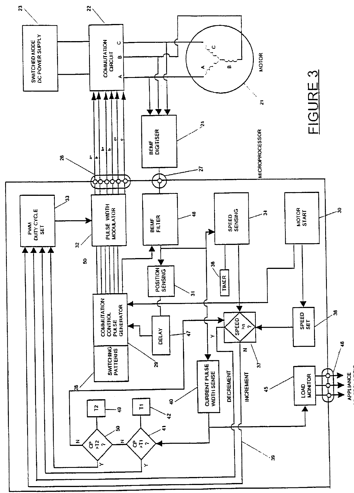
FIG. 3 shows the motor control system of the present invention in block diagram form. The main hardware blocks are a permanent magnet three winding motor 21, motor winding commutation circuit 22, switched mode DC power supply 23, back EMF digitiser 24 and microcomputer 25. The blocks within microcomputer 25 represent functions executed by software routines which will be described below.

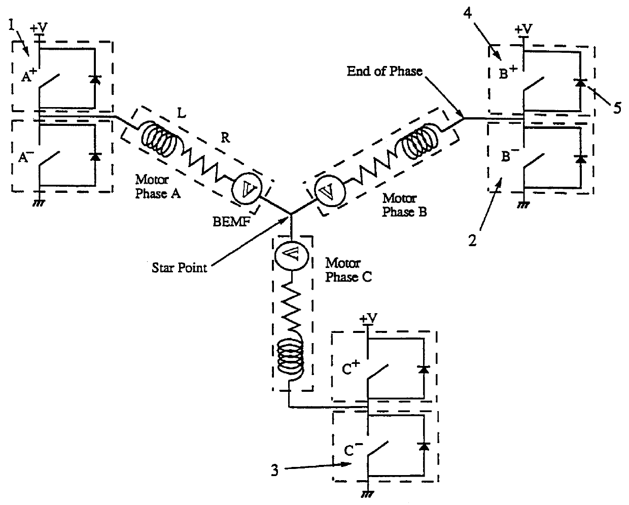
The present ECM system is described in relation to a motor having a stator with three windings (or phases) A, B and C and six salient poles. Other stator configurations could be used. The motor has a four pole permanent magnet rotor, although a different number of poles could be adopted. The windings A, B and C are connected together in star configuration in this embodiment as indicated in FIG. 3.

Commutation circuit 22 includes pairs of switching devices in the form of power field effect transistors (FETs) which are connected across the direct current power supply 23 to commutate each of windings A, B...


PUM


Abstract

An electronically commutated brushless DC motor primarily for fractional horsepower applications of the type where at any instant one motor winding is unpowered and used to detect back EMF zero-crossings which information is used to initiate winding commutations. The duration of the pulse produced in this winding due to dissipation of stored energy by free-wheel diodes in parallel with the commutation devices after supply of current has been removed from this winding is used to provide a measure of motor current. This allows for simplified commutation device current limiting circuits and is available for control purposes which are a function of motor torque. There is also disclosed a method for maximizing useful power output by reducing the phase angle between the motor current and the back EMF. This is accomplished by introducing a delay in commutating the motor windings beyond the occurrence of each back EMF zero-crossing, with the delay being a function of the time between commutations.

Description

This invention relates to electronically controlled brushless DC motors (having permanent magnet rotors) and in particular, but not solely, to three winding motors for fractional horsepower applications such as in home appliances and healthcare equipment.PRIOR ARTMethods of controlling electronically commutated brushless DC motors have been disclosed in U.S. Pat. No. 4,495,450 (Tokizaki et al) and for use in home appliances and in particular laundry washing machines in U.S. Pat. No. 4,540,921 (Boyd et al), U.S. Pat. No. 4,857,814 (Duncan et al). Some of the basic electronically controlled motor (ECM) concepts described in these patents is summarised below with reference to FIGS. 1 and 2.An ideal tree phase (or winding) DC motor is shown in FIG. 1 with commutation switches which would normally be power FETs. By turning on upper switch 1 for phase A and lower switch 2 for phase B, a static magnetic field will be created in the stator. By turning off lower switch 2 for phase B and turn...

Claims


Application Information

Patent Timeline
Patent Type & Authority Patents(United States)
IPC IPC(8): H02P6/14H02P6/00H02P6/18H02K29/00H02P6/06H02P6/16
CPCH02P6/002H02P6/142H02P6/182H02P6/28H02P6/15H02K29/00
Inventor BOYD, JOHN H.DUNCAN, GERALDPERRY, MICHAEL THOMAS GEORGE
Owner FISHER & PAYKEL APPLIANCES LTD
Why Eureka
Try Eureka