Method for producing a laminated object and apparatus for producing the same

a technology of laminated objects and methods, applied in the direction of vehicle route interaction devices, nuclear engineering, railway components, etc., can solve the problems of excessive irradiation energy with respect to the deposited layer, increase the required irradiation time, and disadvantage in high speed production and production ability, so as to prevent overconcentration of laser beams, improve the shape accuracy at the edge of solid layers, and improve the effect of accuracy

Inactive Publication Date: 2000-04-25
TOYOTA JIDOSHA KK
View PDF30 Cites 48 Cited by
  • Summary
  • Abstract
  • Description
  • Claims
  • Application Information

AI Technical Summary

Benefits of technology

According to the first aspect of the present invention, the deposited layer is irradiated with the laser beam, with the deposited layer being covered with the mask; thus, shape accuracy at the edge of the solid layer is improved to secure shape accuracy at the edge of the three-dimensional laminated object even when a spot diameter of the laser beam is increased. The first aspect of the present invention may increase and fit the spot diameter of the laser beam while improving the accuracy, thereby preventing overconcentration of the laser beam so as to suppress overhardness of the deposited layer, in particular, the most outside surface of the deposited layer. As a result, it is advantageous to obtain the sufficient solid layer and the sufficient the laminated object. Further, the first aspect is advantageous in shortening a scann irradiation time to contribute to improvement in production ability, because of increase of the spot diameter of the laser beam.
The first aspect of the present invention uses a scann system in which scann irradiation is carried out by using the X-rotating mirror, thereby improving uniformity of irradiation energy in an irradiation area, which allows the solid layer to be uniformity to form the sufficient laminated object, in comparison with a non-scann system in which a spurious laser beam, generated by means of a kalaid scope method, is emitted.
According to the second aspect of the present invention, before and during the depositing step, at least one of the deposited layer and the material is detected in temperature by using the temperature detecting means, and laser beam energy is increased or decreased depending on the detected temperature results. Thus, the second aspect decreases irradiation energy in the case where temperature in the deposited layer...

Problems solved by technology

This case improves accuracy at the edge of the three-dimensional laminated object; however, this case increases a required irradiation time considerably and causes a disadvantage in high speed production and production ability.
This mode, however, excessively increases irradiation energy with respect to the deposited layer per unit area.
Also, high speed in scanning speed exhibits a limit at a present situation; so, improving production ability is very hard in this method.
This mode, however, trends to cause en...

Method used


Image

  • Method for producing a laminated object and apparatus for producing the same
  • Method for producing a laminated object and apparatus for producing the same
  • Method for producing a laminated object and apparatus for producing the same

Examples


first preferred embodiment

A mask according to the present invention has a function for a laser beam to penetrate thereinto and a function for interrupting penetration of the laser beam. The mask therefore has a beam penetrating portion and a beam interrupting portion. The beam penetrating potion may be an opening in many cases. In the case of a YAG laser beam, it penetrates through transparent quartz glass; thus, the mask may be constituted by printing a beam interrupting film on transparent quartz glass having no openings so as to form the beam interrupting portion and the beam penetrating portion.

A depositing material according to the present invention is to be a solid layer when it is irradiated with a laser beam. The material may be grains, powders, and liquids--grains covered with thermosetting resin, grains and powders made from thermosetting resin, and grains and powders made from metal. These materials form a solid layer by receiving a laser beam. The thermosetting resin may be phenolic resin.

A X-rot...

second preferred embodiment

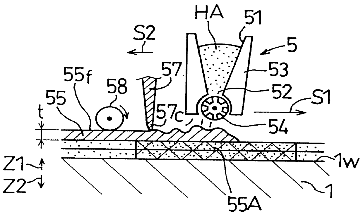
A Second Preferred Embodiment is carried out like the First Preferred Embodiment. A depositing step is characterized in that a depositing apparatus comes into non-contact with a deposited layer. Thus, when the deposited layer has an over thickness portion besides a normal thickness portion, this embodiment may execute a manner that the depositing means always comes into non-contact with the deposited layer. Also, this embodiment may execute a manner that the depositing means comes into non-contact with the normal thickness portion of the deposited layer and that the thickness correcting means comes into contact with the over thickness portion so as to correct the over thickness portion. The thickness correcting means is provided on the depositing apparatus or separated from the depositing apparatus. The depositing apparatus may be in a mode having a roller for discharging the powder or grain material or in another mode spraying with a material or with a material comprising a solvent...

example 1

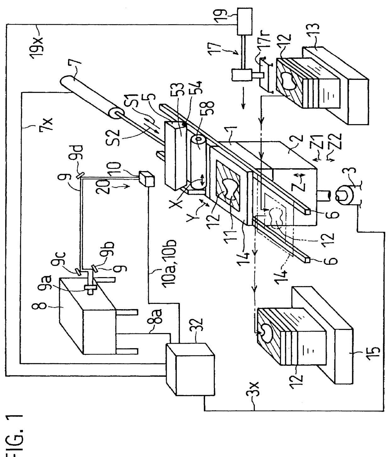
repeatedly carries out the depositing step, the mask exchanging step and irradiating step many times in sequence to produce the three-dimensional laminated object. FIG. 12 shows the diagram with totality of steps, a depositing step using the depositing apparatus 5, and the thickness detecting step for detecting the thickness of the deposited layer.

Control in Example 2

FIG. 13 shows one main-routine flowchart about a control treatment executed with the controller 32. The controller 32 executes an initial set in step S2 to set a depositing flag and a roller flag to "1" in step S4. When such flags are at "1", the controller indicates that layer 55 is to be an odd number, that the depositing apparatus 5 is transferred forward in the S2 direction, and that the cutting roller 54 is rotated in the R1 direction. When such flags are at "0", the controller indicates that the deposited layer 55 is to be an even number, that the depositing apparatus 5 is transferred backward in the S1 direction,...


PUM

PropertyMeasurementUnit
Diameteraaaaaaaaaa
Diameteraaaaaaaaaa
Thicknessaaaaaaaaaa

Abstract

A method for producing a laminated object repeats a depositing step and an irradiating step alternatively. The irriating step comprises the operations of: covering a deposited layer with a mask having a pattern configuration for penetrating the laser beam; and scanning the lader beam on the desposited layer covered with the mask in such a manner that the laser beam depicts an irradiated continous wave trace being wider than the pattern configuration of the mask, by moving the laser beam in the Y-direction with a Y-rotating mirror, while repeating oscillations of the laser beam in the X-direction with a X-rotating nirror, The laminated object may be a casting mold.

Description

1. Field of the InventionThis invention relates to a method and an apparatus for producing a laminated object in which a deposited layer, constituted by depositing a material capable of forming a solid layer, is irradiated with a laser beam to form a solid layer and in which the solid layers are piled to constitute a three-dimensional laminated object.2. Description of the Related ArtA method for producing a laminated object has been developed recently. This method is disclosed in Japanese Unexamined Patent Publication (KOKAI) No.3-183,530, U.S. Pat. No. 4,247,508, and others. This method alternatively repeats a depositing step and an irradiating step. In the depositing step, grains are deposited to constitute a deposited layer. In the irradiating step, the deposited layer is irradiated with a laser beam to constitute a solid layer and a large number of solid layers are piled to produce a three-dimensional laminated object. This method, as appreciated in FIG. 26, has a problem that ...

Claims


Application Information

Patent Timeline
IPC IPC(8): B23K26/06B29C41/34B29C41/36B29C67/00B29C35/08
CPCB23K26/0656B23K26/0807B23K26/0815B29C67/0077B22F3/1055B29C41/36B22F2003/1056B29C2035/0838B23K26/0821B23K26/082B23K26/066B29C64/153Y02P10/25B22F10/28B22F12/49B22F10/366B22F12/90B22F12/41B22F12/44B22F12/50B22F10/37B22F12/224
Inventor OTSUKA, YUKIOOZAKI, MOTOAKISATO, HIROMOTO
Owner TOYOTA JIDOSHA KK
Why Eureka
Try Eureka