Method for joining metallic materials by diffusion bonding and joined structure thereby

a technology of diffusion bonding and metallic materials, which is applied in the direction of non-electric welding apparatus, manufacturing tools, and solvents, etc., can solve the problems of poor economics, fatigue strength, and inability to accept the effect of diffusion bonding, and achieve the effect of strengthening the economics of the economy

Inactive Publication Date: 2000-05-09
SUMITOMO METAL IND LTD
View PDF17 Cites 28 Cited by
  • Summary
  • Abstract
  • Description
  • Claims
  • Application Information

AI Technical Summary

Problems solved by technology

However, some aspects of the property at the bonded joint formed by this method, in particular, fatigue strength, are not acceptable.
The method, however, has a weakness of poor economics, since after diffusion bonding, the arc welding needs to be additionally applied.
The methods for joining described above,may not be appropriate for the specified service environment in which the bonded joint is exposed.
(1) In the case of a martensitic stainless steel, weld metal and heat affected zones are hardened as quenched, and consequently, toughness is degraded and cracking resistance in the humid CO.sub.2 environment containing a trace of H.sub.2 S is impaired.
(2) In the case of an austenitic-ferritic stainless steel (hereinafter referred to as a duplex stainless steel), a proportion of ferrite in weld metal goes up, resultin...

Method used


Image

  • Method for joining metallic materials by diffusion bonding and joined structure thereby
  • Method for joining metallic materials by diffusion bonding and joined structure thereby
  • Method for joining metallic materials by diffusion bonding and joined structure thereby

Examples


embodiment 1

[Embodiment 1]

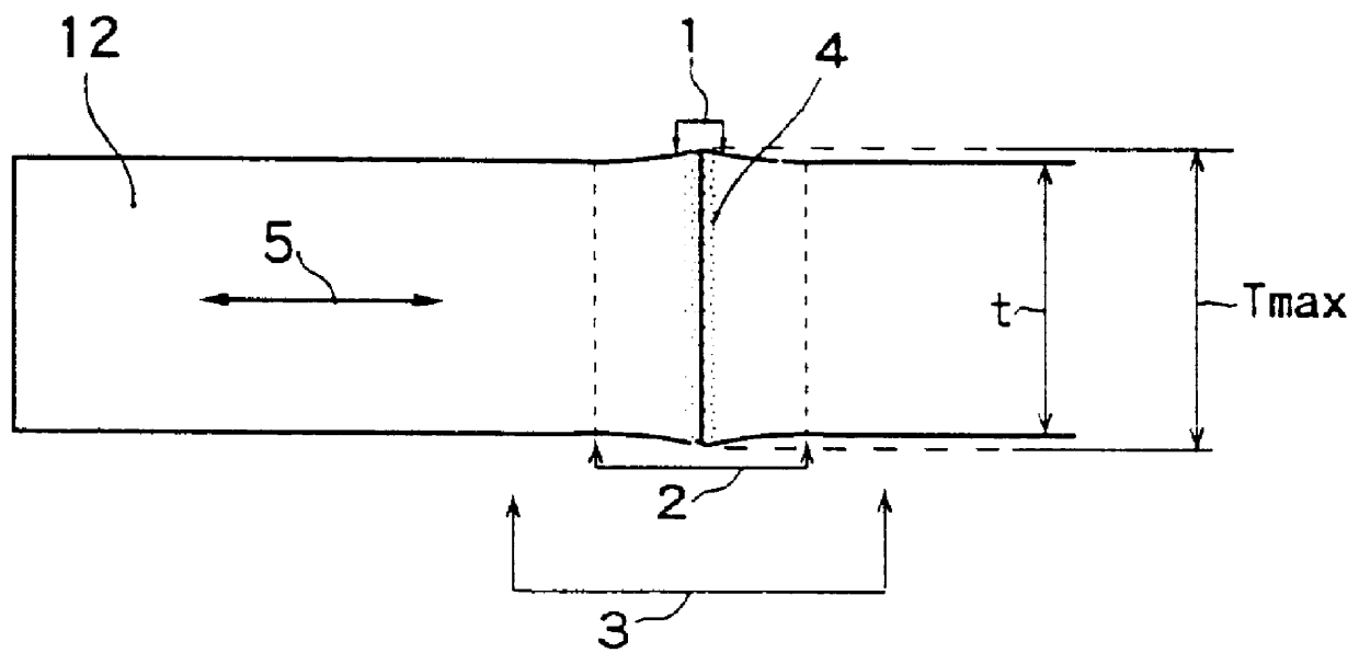
The effect of Invention 1 is described hereafter with reference to Embodiment 1. A seamless steel pipe having chemical composition of 0.24% C, 0.25% Si, 1.13% Mn, 0.48% Cr, 0.026% Ti, and balance substantially Fe, 130 mm in outside diameter and 15 mm in wall thickness, treated by quenching (quenching temperature at 950.degree. C.) and tempering (tempering temperature at 620.degree. C.) was used as the base material. The steel pipe had tensile strength of 860 MPa.

As the bonding material, an insert material of an alloy strip (as referred to in Invention 5) 30 .mu.m thick and having the melting point at 1140.degree. C. and chemical composition of 1.4% B, 7.3% Si, 5.3% Cr, and balance Ni was used.

Diffusion bonding was carried out under a nitrogen gas shield with the conditions of a temperature at the bonded layer 1 being 1250.degree. C. and heating for a retention time of 300 seconds. Heating was applied by means of the high frequency induction heating system with the cond...

embodiment 2

[Embodiment 2]

The effect of Invention 2 is then described with reference to Embodiment 2.

FIG. 4 shows chemical composition of insert materials (referred to in Invention 6) used as the bonding material in tests.

The insert materials were thin steel strips produced by a rapid quenching method wherein molten steel with chemical composition adjusted is dropped on the surfaces of rotating rolls. Thickness of the respective thin steel strips were controlled by the dropping rate of the molten steel and rotating velocity of the rolls and are shown in FIG. 6.

FIG. 5 shows chemical composition and YS of martensitic and duplex stainless steel pipes. All these steel pipes were seamless steel pipes 130 mm in outside diameter and 15 mm in wall thickness.

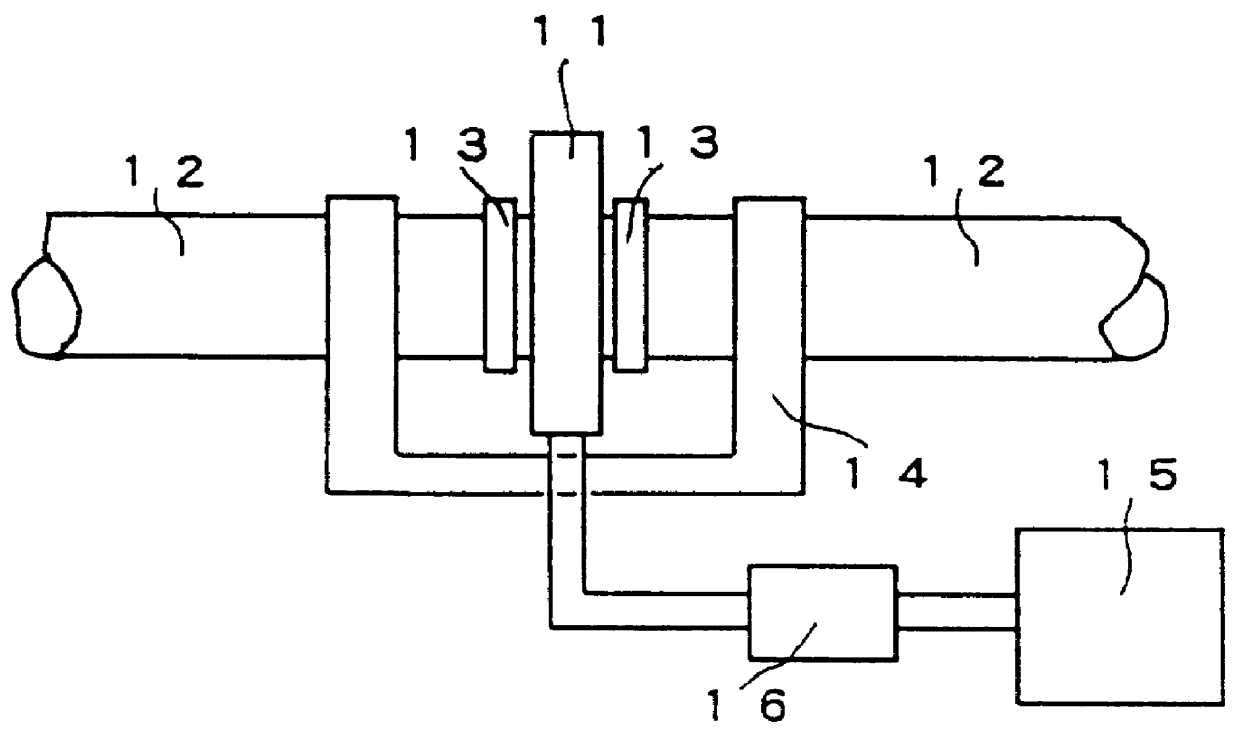
As in the case of embodiment 1, diffusion bonding was carried out in the apparatus,which was prepared by modifying the one shown in FIG. 2. Adjustment of the heated length was made by varying the width of the heating coil in the range of 10 to 50 mm...


PUM

PropertyMeasurementUnit
Lengthaaaaaaaaaa
Timeaaaaaaaaaa
Pressureaaaaaaaaaa

Abstract

The present invention provides (1) diffusion bonding methods for joining metallic materials like carbon steels or stainless steels,interposing a bonding material, such as 10 to 80 mu m thick Ni-based alloy with the melting point of 1150 DEG C. or lower,between base materials, heating so that the length heated at 800 DEG C. or above measures from 3 to 20 mm, in case of joining stainless steels a bonded layer, further, being heated between the both melting points, and applying the compressive stress, for example 0.5 to 2 kgf/mm2, so that a lateral expansion ratio is made within 1.0 to 1.1, and (2) a joined structure having the bonded joint formed thereby.

Description

The present invention relates to a method for joining metallic structural members such as stainless steels, and the like, which are highly corrosion resistant in a humid CO.sub.2 environment containing a trace of H.sub.2 S, and particularly, a method for joining oil countries tublar goods including coiled tubing.BACKGROUND TECHNOLOGYA method for joining metallic materials by diffusion bonding has recently attracted much attention because of its characteristics that the bonded joint is not susceptible to degradation in quality and bonding is achieved easily without affecting the qualities of materials bonded. Hence, a number of inventions related thereto have been disclosed (for example, Japanese Patent Laid-open Publication No. Hei 6-7967, Hei 5-169280, Hei 5-161984, Hei 5-77063, Hei 5-220585, Hei 2-75478 etc.). In this description, "metallic materials" and "base materials" referred to hereinafter mean the same object.Among the methods of diffusion bonding described above, a method ...

Claims


Application Information

Patent Timeline
IPC IPC(8): B23K20/16B23K35/30B23K35/00B23K35/38B23K35/22
CPCB23K20/16B23K35/004B23K35/3033B23K2203/04B23K35/304B23K35/383B23K2103/04B23K2103/05
Inventor HAMADA, MASAHIKOFUKADA, YASUTOUEDA, MASAKATSUKOMIZO, YUUICHI
Owner SUMITOMO METAL IND LTD
Why Eureka
Try Eureka