Digital pulse filtering circuit

a filtering circuit and digital pulse technology, applied in the direction of pulse characteristics measurement, amplitude demodulation, line-fault/interference reduction, etc., can solve the problems of large space on the circuit board, large resistor and capacitor constituents occupying quite a large space, and increasing manufacturing costs

Inactive Publication Date: 2000-05-16
UNITED MICROELECTRONICS CORP
View PDF6 Cites 15 Cited by
  • Summary
  • Abstract
  • Description
  • Claims
  • Application Information

AI Technical Summary

Problems solved by technology

One drawback to these analog filters is that their constituent resistors and capacitors take up quite a large space on the circuit boards.
Moreover, when the pulses that are to be filtered out are very large in pulse width, the analog filters require the use of large-resistance resistors and large-capacitance capacitors to implement, which take up an even larger space on the circuit boa

Method used


Image

  • Digital pulse filtering circuit
  • Digital pulse filtering circuit
  • Digital pulse filtering circuit

Examples


Embodiment Construction

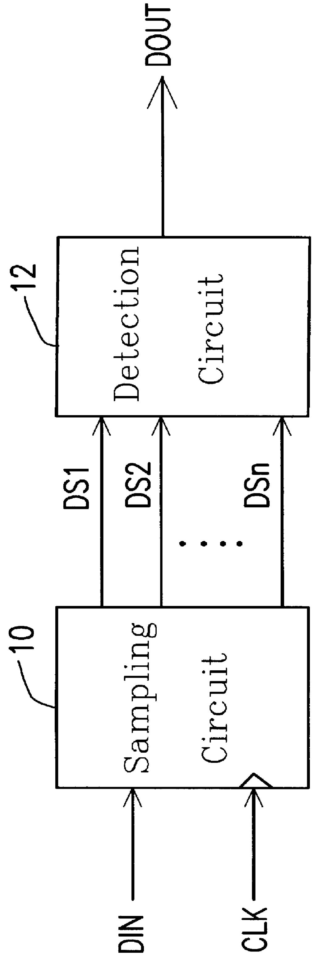
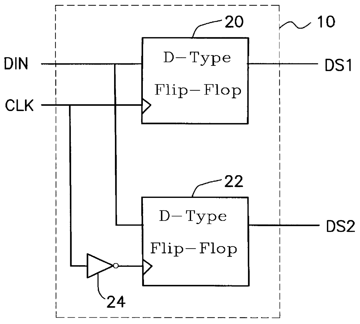
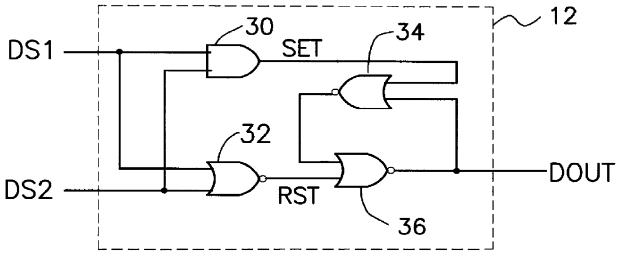
FIG. 1 is a schematic block diagram of the digital pulse filtering circuit according to the invention. As shown, the digital pulse filtering circuit of the invention includes a sampling circuit 10 and a detection circuit 12. The sampling circuit 10 is used to sample an input composite signal DIN under control by a clock signal CLK to thereby generate a number of sampled signals DS1, DS2, . . . , DSn of the input composite signal DIN. In response to these signals DS1, DS2, . . . , DSn, the detection circuit 12 generates a low-frequency composite signal DOUT which is a low-pass filtered version of the input composite signal DIN. First, the detection circuit 12 checks these signals DS1, DS2, . . . , DSn to see if they are all equal in logic value (voltage state); if YES, the current state of the low-frequency composite signal DOUT will be changed to the present state of these signals DS1, DS2, . . . , DSn; and otherwise, the current state of the low-frequency composite signal DOUT will...


PUM


Abstract

A digital pulse filtering circuit for filtering out pulses of specific pulse widths in a composite signal is provided. The digital pulse filtering circuit includes a sampling circuit for sampling the input composite signal based on a periodic clock signal to thereby generate a plurality of sampled signals of the input composite signal. In response to these sampled signals, a detection circuit outputs a low-frequency composite signal which is a filtered version of the input composite signal. The digital pulse filtering circuit is completely based on digital circuitry which can be built in integrated circuits. The cutoff frequency of the digital pulse filtering circuit is dependent on the frequency of the clock signal, which is very easy and accurate to adjust.

Description

1. Field of the InventionThis invention relates to filtering circuits, and more particularly, to a digital pulse filtering circuit which can filter out pulses of specific widths in a composite signal and which is constructed completely based on digital circuitry.2. Description of Related ArtIn conventional monitors, a composite signal comprises all the sync signals necessary for proper operation of the monitors. These sync signals include a vertical sync signal and a horizontal sync signal. The composite signal can be either positive or negative in polarity. In practice, the horizontal sync signal is a first periodic pulse train having a period of from 8.33 .mu.s (microsecond) to 33.33 .mu.s and a pulse width of from 1.0 .mu.s to 3.92 .mu.s; while the vertical sync signal is a second periodic pulse train having a period of from 8.33 ms (millisecond) to 25 ms and a pulse width from 0.0384 ms to 0.125 ms.Given a composite signal, the vertical sync component can be obtained by filterin...

Claims


Application Information

Patent Timeline
IPC IPC(8): H03K5/125
CPCH03K5/125
Inventor LIU, DONTAI, NEIL
Owner UNITED MICROELECTRONICS CORP
Why Eureka
Try Eureka