Method for interferometer based spectral imaging of moving objects

Inactive Publication Date: 2000-07-11
APPLIED SPECTRAL IMAGING
View PDF3 Cites 30 Cited by
  • Summary
  • Abstract
  • Description
  • Claims
  • Application Information

AI Technical Summary

Benefits of technology

The present invention successfully addresses the shortcomings of the presently known configurations by providing an interferometer based spectral imaging method which perm

Problems solved by technology

The inability to visualize the two-dimensional image before the whole measurement is completed, makes it impossible to choose, prior to making the measurement, a desired region of interest from within the field of view and/or to optimize the system focus, exposure time, etc.
It should be further noted that slit-type imaging spectrometers have a major disadvantage since most of the pixels of one frame are not measured at any given time, even though the fore-optics of the instrument actually collects incident light from all of them simultaneously.
Furthermore, slit-type spectral imagers require line scanning to collect the necessary information for the whole scene. which may introduce inaccuracies to the results thus obtained.
However, AOTFs and LCTFs have the disadvantages of (i) limited spectral range (typically, .lambda..sub.max =2.lambda..sub.min) while all other radiation that falls outside of this spectral range must be blocked, (ii) temperature sensitivity, (iii) poor transmission, (iv) polarization sensitivity, and (v) in the case of AOTFs an

Method used


Image

  • Method for interferometer based spectral imaging of moving objects
  • Method for interferometer based spectral imaging of moving objects
  • Method for interferometer based spectral imaging of moving objects

Examples


example 1

Spatial Registration and Spectral Correction--the Effect on the Image

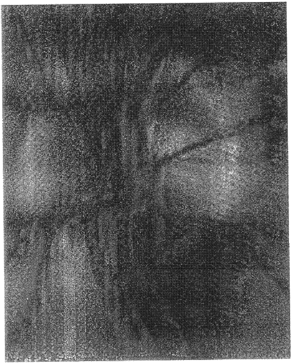
With reference now to FIGS. 3a and 3b. FIG. 3a presents a spectral image of the optic disc of the retina of a right eye of a healthy individual using the SpectraCube.TM. system, while not employing spatial registration and spectral correction procedures as described in accordance with the method of the present invention. FIG. 3b, on the other hand, presents the very same image after spatial registration and spectral correction procedures according to the present invention.

In both images the optic disc appears lighter in the middle portion of the image along with blood vessels nourishing the optical nerve with oxygen and other nutrients (arterioles) and removing waste and carbon dioxide generated during metabolism (veins). However, as is clearly evident comparing the two images, due to movements of the eye during measurement, the image of FIG. 3a is highly blurred. Corrective action according to the method of the pr...

example 2

Spectral Correction--the Effect on the Interferogram

With reference now to FIGS. 4a and 4b. FIG. 4a presents a portion of an interferogram calculated for a single pixel (x=112, y=151) of the image presented in FIG. 3a, i.e., while not employing spatial registration and spectral correction procedures as described in accordance with the method of the present invention. FIG. 3b, on the other hand, presents the corresponding portion of an interferogram of the very same pixel after spatial registration and spectral correction procedures according to the present invention.

Examining the interferogram of FIG. 3a reveals that the left and central parts of the function (measured in equal intervals of time) resembles a typical interferogram, whereas the right portion of the function, is totally atypical. The local maximum indicated by an arrow is due to sudden motion of the examined object (e.g., a saccadic motion of the eye). The uncharacteristic increase of signal is due to the fact that a di...

example 3

Spectral Correction--the Effect on the Spectrum

With reference now to FIGS. 5a and 5b. FIG. 5a presents spectra of five adjacent pixels derived from the image of FIG. 3a, while not employing spatial registration and spectral correction procedures as described in accordance with the method of the present invention. Four of these pixels

are centered around the fifth which is the pixel whose interferogram is shown in FIG. 4a. FIG. 5b, on the other hand, presents spectra of the same five pixels after application of the spatial registration and spectral correction procedures according to the present invention. The dip around 575 nm is characteristic of oxyhemoglobin absorption.

Comparing the spectra of FIGS. 5a and 5b, one notices two phenomena. First, corresponding spectra are much noisier in FIG. 5a as compared with FIG. 5b. Second, when implementing the method of the present invention, as shown in FIG. 5b, from pixel to pixel the spectra change in a uniform pattern presenting an expected...


PUM


Abstract

A method for spatial registration and spectral correction for interferometer based spectral imaging which can be used to obtain spectral images of a moving object, the method comprising the steps of (a) using an interferometer based spectral imager for acquiring spatial and spectral information of the moving object; and (b) correcting the spatial and spectral information for movements of the moving object via a spatial registration and spectral correction procedures for obtaining corrected spatial and spectral information.

Description

FIELD AND BACKGROUND OF THE INVENTIONThe present invention relates to a method for spectral analysis of objects, i.e., spectral imaging. More particularly the present invention relates to an interferometer based method aimed at spectral imaging of a moving object, to determine the spectral intensity of each pixel thereof. Spectral intensity according to the invention may be due to light emitted (naturally occurring or induced fluorescence) from, reflected or scattered by and / or transmitted through the moving object, all are further referred hereinbelow as light emitted from the object.Spectroscopy is a well known analytical tool which has been used for decades in science and industry to characterize materials and processes based on the spectral signatures of chemical constituents. The physical basis of spectroscopy is the interaction of light with matter. Traditionally, spectroscopy is the measurement of the light intensity emitted, transmitted, scattered or reflected from an object...

Claims


Application Information

Patent Timeline
IPC IPC(8): G01B9/02
CPCG01B9/02
Inventor CABIB, DARIOBUCKWALD, ROBERT A.
Owner APPLIED SPECTRAL IMAGING
Why Eureka
Try Eureka