Blazed grating measurements of lithographic lens aberrations

a lithographic lens and aberration technology, applied in the field of testing and characterization of lenses, can solve the problems of severe and unavoidable physical limitations relating to the exposure, the feature size required by modern integrated circuits, and the general impracticality of x-rays for semiconductor fabrication

Inactive Publication Date: 2000-07-18
GLOBALFOUNDRIES INC
View PDF2 Cites 50 Cited by
  • Summary
  • Abstract
  • Description
  • Claims
  • Application Information

AI Technical Summary

Problems solved by technology

Lithographic processes, however, at the feature sizes required by modern integrated circuits, are subject to severe and unavoidable physical limitations related to how the exposure is made.
While X-rays have been investigated and used for lithographic exposures, the nature of the required mask and difficulty of fabrication thereof at the present state of the art renders X-rays generally impractical for semiconductor fabrication and charged particle beam tools are often used when extremely small feature sizes must be obtained.
However, throughput of charged particle beam tools is relatively low and optical exposure at short wavelengths (e.g. deep ultra-violet) remains the exposure medium of choice for most integrated circuit manufacture.
However, aberrations (e.g. localized shift of focus or departure from planarity of the best focussed image) in the projection lens system have become increasingly critical and, at the current state of the art, are a fundamental limitation on exposure tool performance.
While some precorrections may be made if the aberrations are well-understood, such information is difficult to obtain with suitable accuracy for this purpose and seldom supplied by the lens...

Method used


Image

  • Blazed grating measurements of lithographic lens aberrations
  • Blazed grating measurements of lithographic lens aberrations
  • Blazed grating measurements of lithographic lens aberrations

Examples


Embodiment Construction

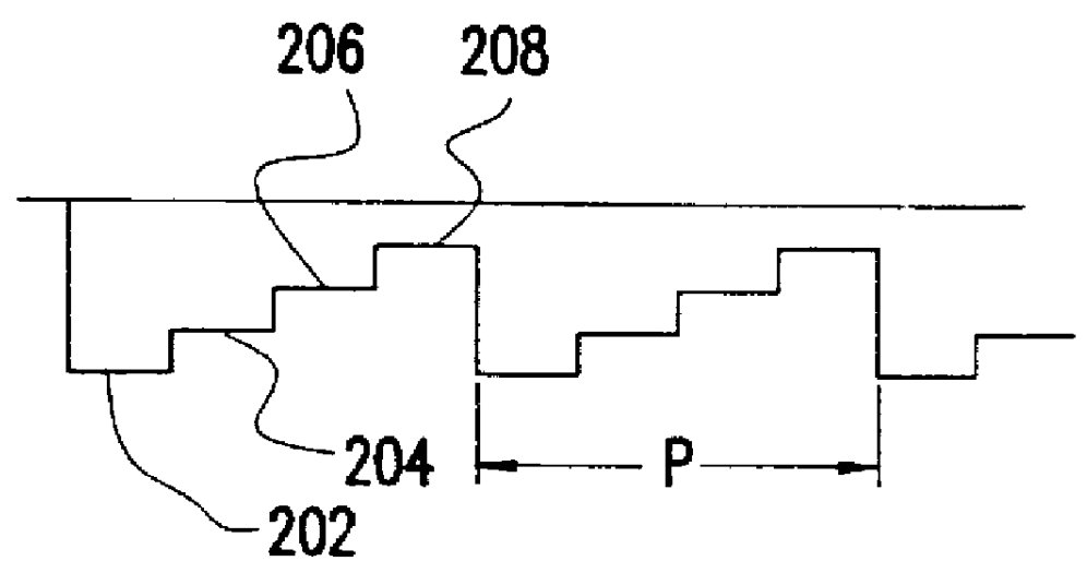
Referring now to the drawings, and more particularly to FIG. 1A, there is shown, in cross-section, an amplitude grating 100 of a known type. The illumination pattern produced at the lens pupil is illustrated in FIGS. 1B and 1C. Specifically, grating 100 provides a regular pattern of opaque areas 110 and transparent areas 120, typically in the form of lines extending into and out of the page, as illustrated. As is known, such a grating produces interference effects in dependence on the relationship between the illuminating light wavelength and the dimensions of the opaque and transparent regions 110, 120.

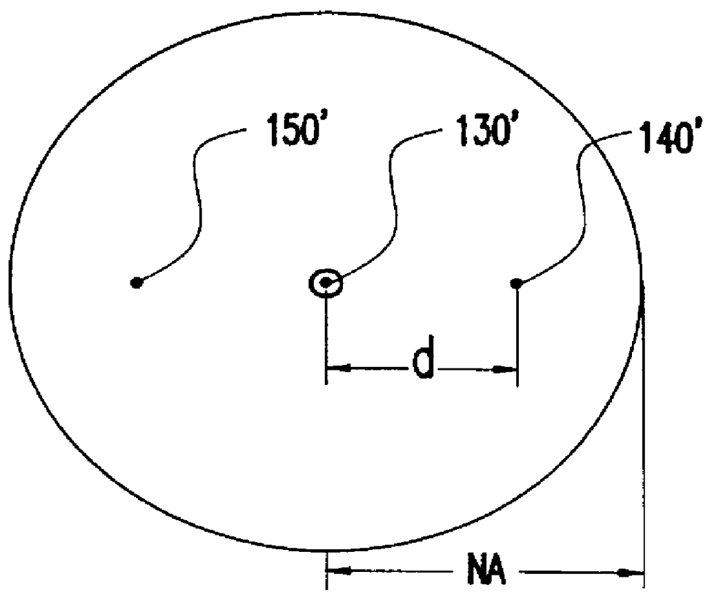
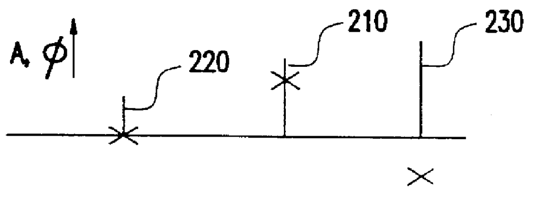
These interference effects cause a variation in illumination amplitude and phase at different locations in the plane of the lens pupil (e.g. center of the lens system), as illustrated in FIG. 1B and 1C. The central illumination component 130' and the first order diffraction components 140' and 150' are schematically depicted as distributed across the pupil having a numerical aperture...


PUM


Abstract

Exposures of a photosensitive material through an array of blazed gratings illuminate a lens asymmetrically to detect effects of a plurality of azimuthal aberrations including coma, astigmatism, and three-leaf and four-leaf clover aberrations. A plurality of such exposures of the array of blazed gratings at slightly differing focus allows detection of focus shift due to any aberrations present in the lens. Upon development of the plurality of exposures, contrast of each area is measured, for example, by reflection or scattering from the relief in the developed photosensitive material and the aberrations thus detected can be simulated by effective summation of individual aberration effects.

Description

1. Field of the InventionThe present invention generally relates to testing and characterization of lenses and, more particularly, to the quantitative measurement of radially asymmetric aberrations in lithographic lenses.2. Description of the Prior ArtLithography is used in numerous manufacturing processes, especially where complex patterning for selective processing at a surface is required. For that reason, lithography is of extreme importance in the manufacture of semiconductor devices and high density integrated circuits, in particular. High density of integration yields both functional and economic advantages in integrated circuits since close spacing of components reduces signal propagation time and increases noise immunity while allowing more chips of increased functionality to be produced by a single iteration of a series of process steps on each wafer. Integration density has also been enhanced by the exploitation of various self-aligned processes with can develop features ...

Claims


Application Information

Patent Timeline
IPC IPC(8): G03F1/14G01M11/02G02B5/18G03F7/20G03F7/207
CPCG01M11/0242G01M11/0271G02B5/1871G03F7/70283G03F7/705G03F7/706G03F7/70641
Inventor KIRK, JOSEPH P.
Owner GLOBALFOUNDRIES INC
Why Eureka
Try Eureka