

Detecting anomalies in rotating components
- Summary
- Abstract
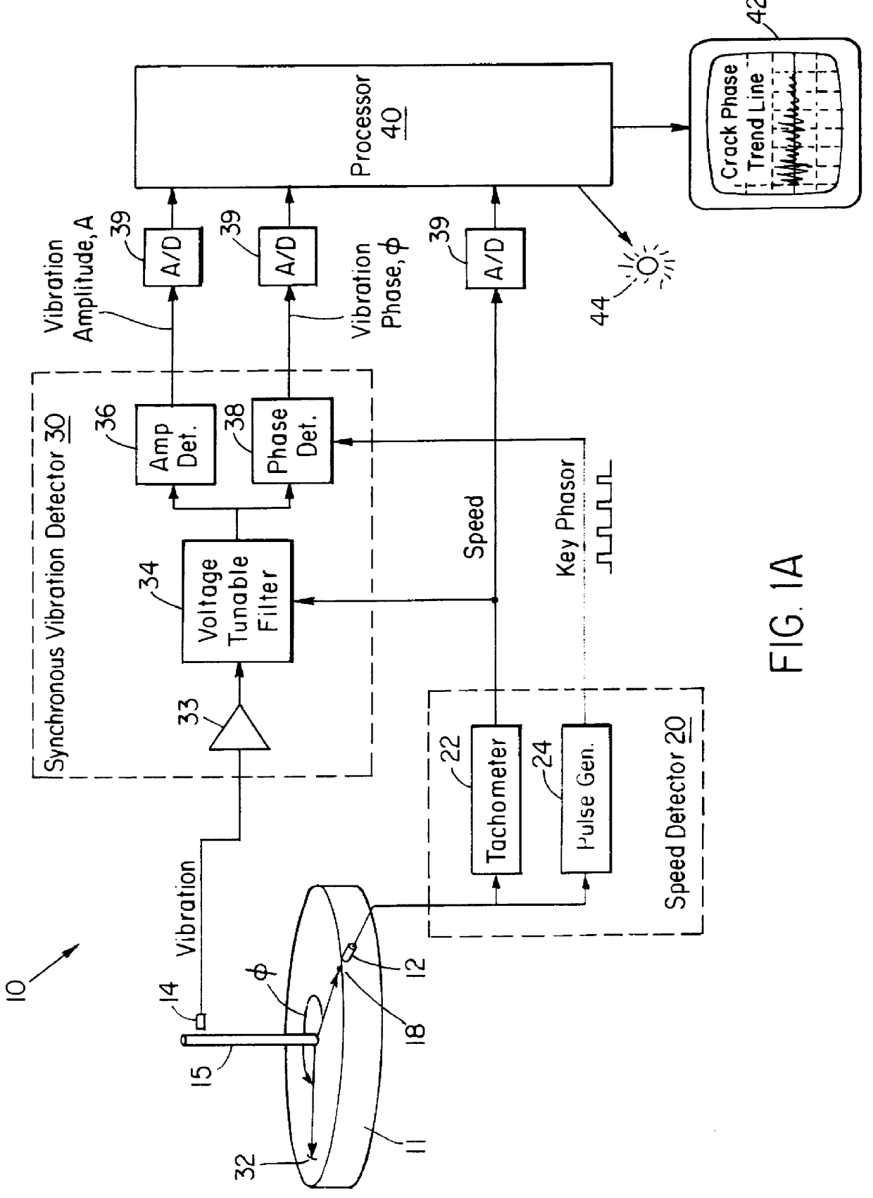
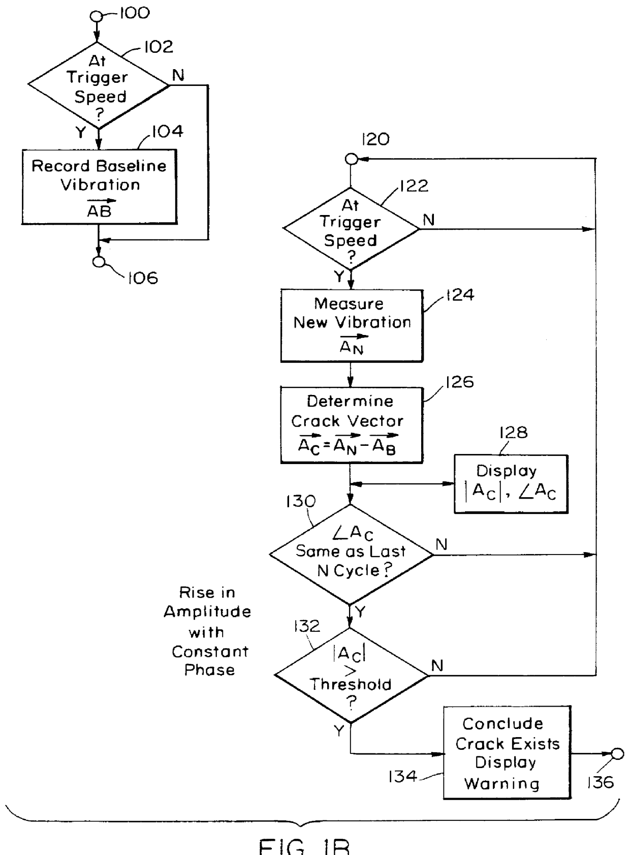
- Description
- Claims
- Application Information
AI Technical Summary
Benefits of technology
Problems solved by technology
Method used
Image

Examples
example i
High-Pressure Turbine (Bladed Disk Assembly)
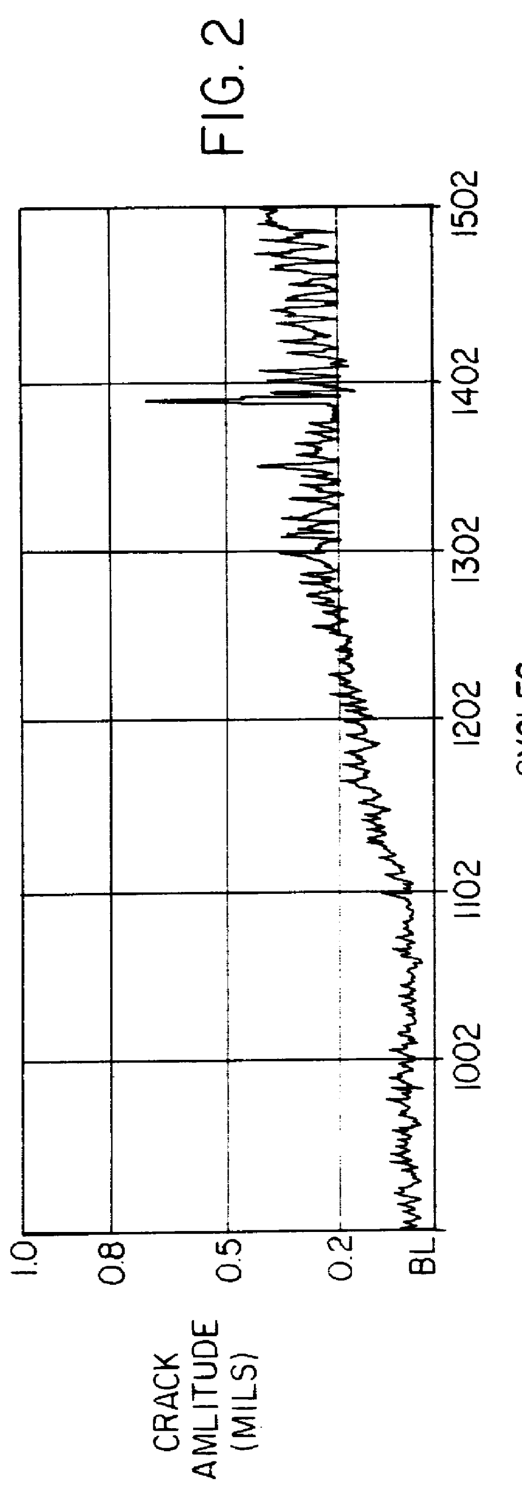
An example application is shown in FIGS. 2-5. This was a low-cycle fatigue test for life certification of a bladed turbine assembly for a jet engine gas generator. The disk was about eight inches in diameter and weighed 15 pounds (lbs.). The test specification called for 30,000 cycles between minimum and maximum speeds of 2,500 revolutions per minute (RPM) and 48,000 RPM. The crack detection system monitored the vibration and crack development. Through 25,000 cycles (1100 on FIG. 2), the system indicated an insignificant crack amplitude, and the crack phase was random (see FIG. 4), a clear indication that no crack has been detected. Beyond 25,000 cycles the initiation of a crack is indicated, as demonstrated by the trend of the crack amplitude (see FIGS. 2 & 3) and crack phase curves (see FIGS. 4 & 5).
As the amplitude of the crack grew, the phase stabilized around a particular angle. During the next 1000 cycles the crack propagation contin...
example ii
Power Turbine (Bladed Disk Assembly)
In this example, a low-cycle fatigue test was performed on a series of power turbine disks. The test was performed in a degraded vacuum which eliminated fretting as an issue during the spin test. A number of tests were run and different failures were recorded and observed with the crack detection system as discussed below.
FIG. 6 is a plot of crack amplitude for one of the power turbine disks. This disk developed cracks in blade tenons. At test termination (approximately 32,000 cycles) this disk had 16 cracks approximately 0.200 inches in size. The crack detection system successfully picked up the initial crack and was able to track crack growth through multiple crack initiations for more than 17,000 low-cycle-fatigue cycles. FIG. 7 shows the phase plot of the crack detection system for this test. It is clear from the undulations in the graph that past cycle 15,000 the system is as tracking multiple cracks, growing at different rates.
PUM
 Abstract
Description
Claims
Application Information