Radiation thermometer

a technology of radiation thermometer and light guide tube, which is applied in the direction of heat measurement, optical radiation measurement, instruments, etc., can solve the problems of probe, probe, and probe diameter to become larger, and the inner surface of the light guide tube 8 to remain more or less

Inactive Publication Date: 2000-08-15
CITIZEN WATCH CO LTD
View PDF9 Cites 14 Cited by
  • Summary
  • Abstract
  • Description
  • Claims
  • Application Information

AI Technical Summary

Problems solved by technology

The application of the coating, however, will not allow the inner surface of the light guide tube 8 to become a perfect reflector having a reflective index of 1.00 and thus cause the inner surface of the light guide tube 8 to remain more or less radiative.
There exists the problem, however, that providing two light guide tubes or fibers as conventionally done causes the diameter of the top-end for facing to the temperature-measured object, that is, the probe, to become larger to accommodate two or more light guide tubes or fibers.
Especially for a radiation clinical thermometer which is inserted into the meatus auditorius externus to detect the infrared radiation from the eardrum, there exists a problem that a radiation clinical thermometer with a probe of a large diameter has difficulty in inserting the radiation clinical thermometer into the meatus auditorium externus to face to the eardrum of a child whose ear hole is small.
To overcome this problem, it may be considered to make the two light guide tubes etc. thinner, however, this causes the emission outlet of the light guide tubes to become smaller and also the original view of the infrared sensor to become smaller due to the emission outlet.
Additionally this causes the incident energy to decrease to lead to a decrease in sensitivity.
Generally, making the view narrower tends to lead to decreasing the incident energy.
Taking into account that energy is lost at every reflection, sensitivity is disadvantageously affected in this point.

Method used


Image

  • Radiation thermometer
  • Radiation thermometer
  • Radiation thermometer

Examples


first embodiment

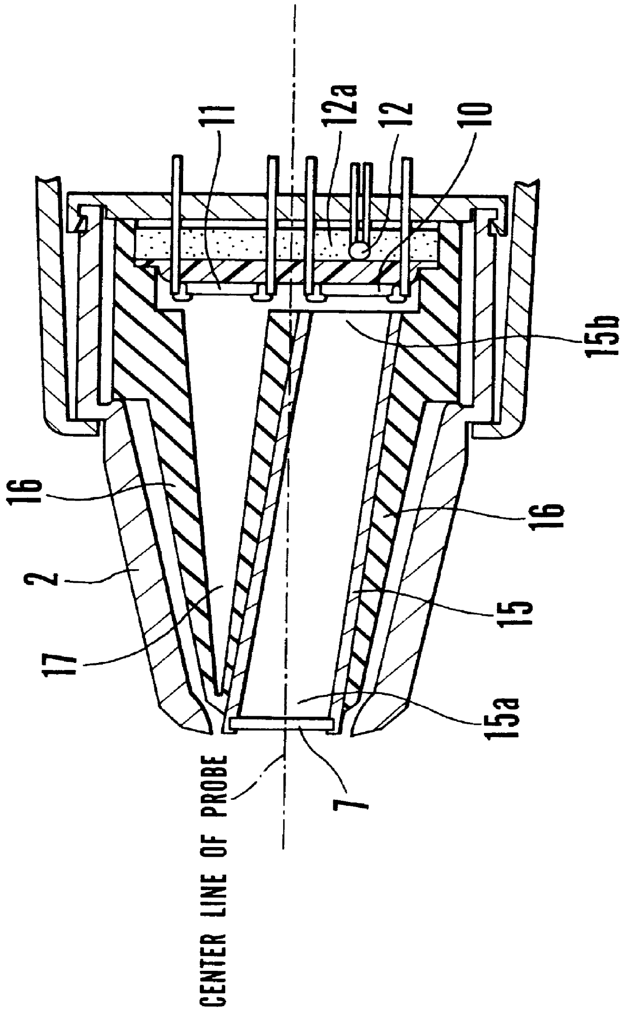
FIG. 1 is a partially cut-out cross-section view showing the probe of the radiation clinical thermometer in accordance with the present invention. The material of the probe 2 is, for example, ABS resin, and the probe 2 is provided inside with the light guide tube 15 and supporting member 16.

The light guide tube is a pipe which is provided to efficiently converge the thermal radiation from the eardrum the temperature of which is to be measured, made of metal such as copper, brass, or stainless steel, and the inner surface of which is a mirror-finished surface coated with gold (Au) to increase the reflectivity.

The light guide tube 15 is provided on the top-end thereof with the filter 7 having transmission wavelength characteristics The filter 7, a dustproof window member for transmitting infrared radiation, is formed by optical crystal such as silicon (Si) or barium fluoride (BaF.sub.2), or a polymer such as polyethylene, and selectively transmits infrared-wavelength radiation. The li...

second embodiment

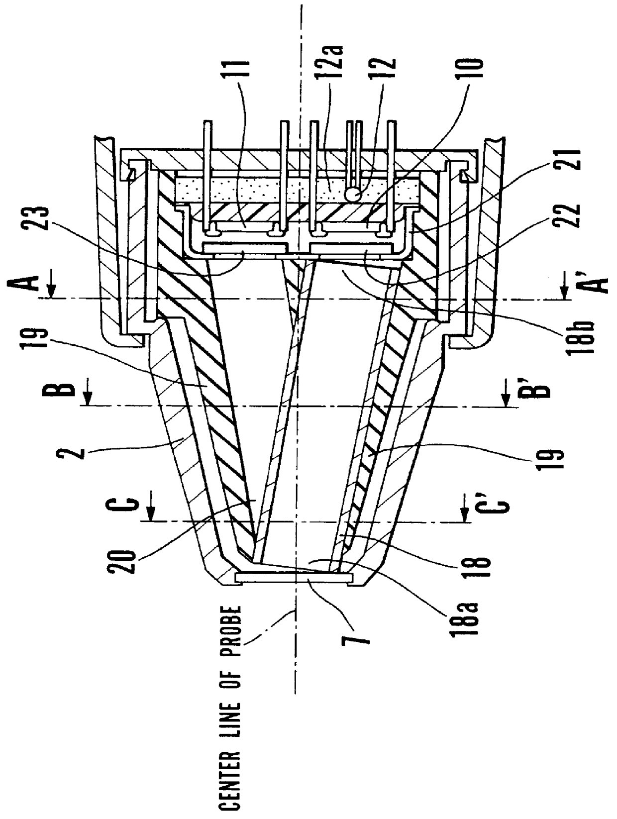
FIG. 3 is a partially cut-out cross-section view showing the probe of the radiation clinical thermometer in accordance with the present intention.

The material of the probe 2 is, for example, ABS resin, and the probe 2 is provided inside with the light guide tube is and supporting member 19.

The light guide tube 18 is a pipe to efficiently converge the thermal radiation from the eardrum the temperature of which is to be measured, is made of metal such as copper, brass, or stainless steel, and has an inner surface which is mirror-finished and coated with gold (Au) to increase the reflectivity.

The probe 2 is provided on the top-end thereof with the filter 7 hating transmission wavelength characteristics. The filter 7, a dustproof window member for transmitting infrared radiation, is formed by optical crystal such as silicon (Si) or barium fluoride (BaF.sub.2), or a polymer such as polyethylene, and selectively transmits infrared-wavelength radiation. In this embodiment, the filter 7 is ...

third embodiment

FIG. 5 is a partially cut-out cross-section view showing the probe of the radiation clinical thermometer in accordance with the present invention. The material of the probe 2 is, for example, ABS resin, and the probe 2 is provided inside the same with the light guide tube 24 and supporting member 25.

The light guide tube 24 is a pipe which is provided to efficiently converge the thermal radiation from the eardrum the temperature of which is to be measured, is made of metal such as copper, brass, or stainless steel, and has an inner surface which is mirror-finished and coated with gold (Au) to increase the reflectivity.

The probe 2 is provided on the top-end thereof with the filter 7 having transmission wavelength characteristics. The filter 7, a dustproof window member for transmitting infrared radiation, is formed by optical crystal such as silicon (Si) or barium fluoride (BaF.sub.2), or a polymer such as polyethylene, and effectively transmits infrared-wavelength radiation.

The suppo...


PUM

PropertyMeasurementUnit
temperatureaaaaaaaaaa
thermal conductivityaaaaaaaaaa
temperature sensitiveaaaaaaaaaa

Abstract

PCT No. PCT / JP97 / 03977 Sec. 371 Date Jul. 10, 1998 Sec. 102(e) Date Jul. 10, 1998 PCT Filed Oct. 31, 1997 PCT Pub. No. WO98 / 20790 PCT Pub. Date May 22, 1998The radiation clinical thermometer of the present invention is provided with a light guide tube 15 to guide the infrared radiation from the temperature-measured object, a first infrared sensor 10 for detecting the infrared radiation from the light guide tube 15, a temperature sensitive sensor 12 which generates a reference temperature signal, a reference cavity 17 which has approximately the same temperature condition as the light guide tube 15 and is sealed so as to shut out infrared radiation from outside, a second infrared sensor 11 for detecting the infrared radiation from the reference cavity 17, a temperature computing means 13 for calculating temperature in accordance with the signals from the first infrared sensor 10 and the second infrared sensor 11, a temperature sensitive sensor 12, and a display unit 14 for displaying temperature in accordance with the signal from the temperature computing means 13; and at least either the light guide tube 15 or the reference cavity 17 is tapered off toward the emission inlet of the light guide tube 15 from the first or second infrared sensor 10 or 11 side.

Description

The present invention relates to a radiation clinical thermometer which detects thermal radiation energy to measure temperature without contact.RELATED ARTSTo measure body temperature in a short period of time, a radiation clinical thermometer which allows one to choose the eardrum for measuring the temperature thereof without contacting the same has been suggested.For example, the present applicant proposed the radiation clinical thermometer shown in FIGS. 10 and 11 in Japanese Patent Application No-Hei-7-294117. FIG. 10 is a front elevation view showing the radiation clinical thermometer proposed in Japanese Patent Application No. Hei-7-294117.The radiation clinical thermometer 1 is a clinical thermometer designed to measure the temperature of the eardrum comprising a main body 4 and a probe 2. The main body 4 is provided with a liquid crystal display element 6 for displaying the body temperature and a measurement switch 5 of a push button structure.The radiation clinical thermome...

Claims


Application Information

Patent Timeline
Patent Type & Authority Patents(United States)
IPC IPC(8): G01K13/00A61B5/01G01J5/02G01J5/04G01J5/00G01J5/54
CPCG01J5/04G01J5/045G01J5/049G01J5/08G01J5/0818G01J5/0875G01J2005/066G01J2005/068H01L2224/48091H01L2924/00014G01J5/064
Inventor EGAWA, SHUNJI
Owner CITIZEN WATCH CO LTD
Why Eureka
Try Eureka