Method of reducing the flow of gas needed for a chamber with controlled temperature and controlled composition of gas

a technology of gas composition and gas flow, which is applied in the direction of muffle furnaces, lighting and heating apparatus, furnaces, etc., can solve the problems of increased design complexity, cost, and involvement, and achieve the effect of reducing the consumption of inertant gas

Inactive Publication Date: 2000-08-22
MATERNA PETER A
View PDF12 Cites 16 Cited by
  • Summary
  • Abstract
  • Description
  • Claims
  • Application Information

AI Technical Summary

Benefits of technology

Accordingly, it is an object of this invention to reduce the consumption of inertant gas which is required by a temperature conditioning chamber due to interchange of gas at the ports of the chamber.

Problems solved by technology

However, this does involve added design complexity and expense mainly related to the changes of direction and complexity of motion of the conveyor.

Method used


Image

  • Method of reducing the flow of gas needed for a chamber with controlled temperature and controlled composition of gas
  • Method of reducing the flow of gas needed for a chamber with controlled temperature and controlled composition of gas
  • Method of reducing the flow of gas needed for a chamber with controlled temperature and controlled composition of gas

Examples


embodiment 2

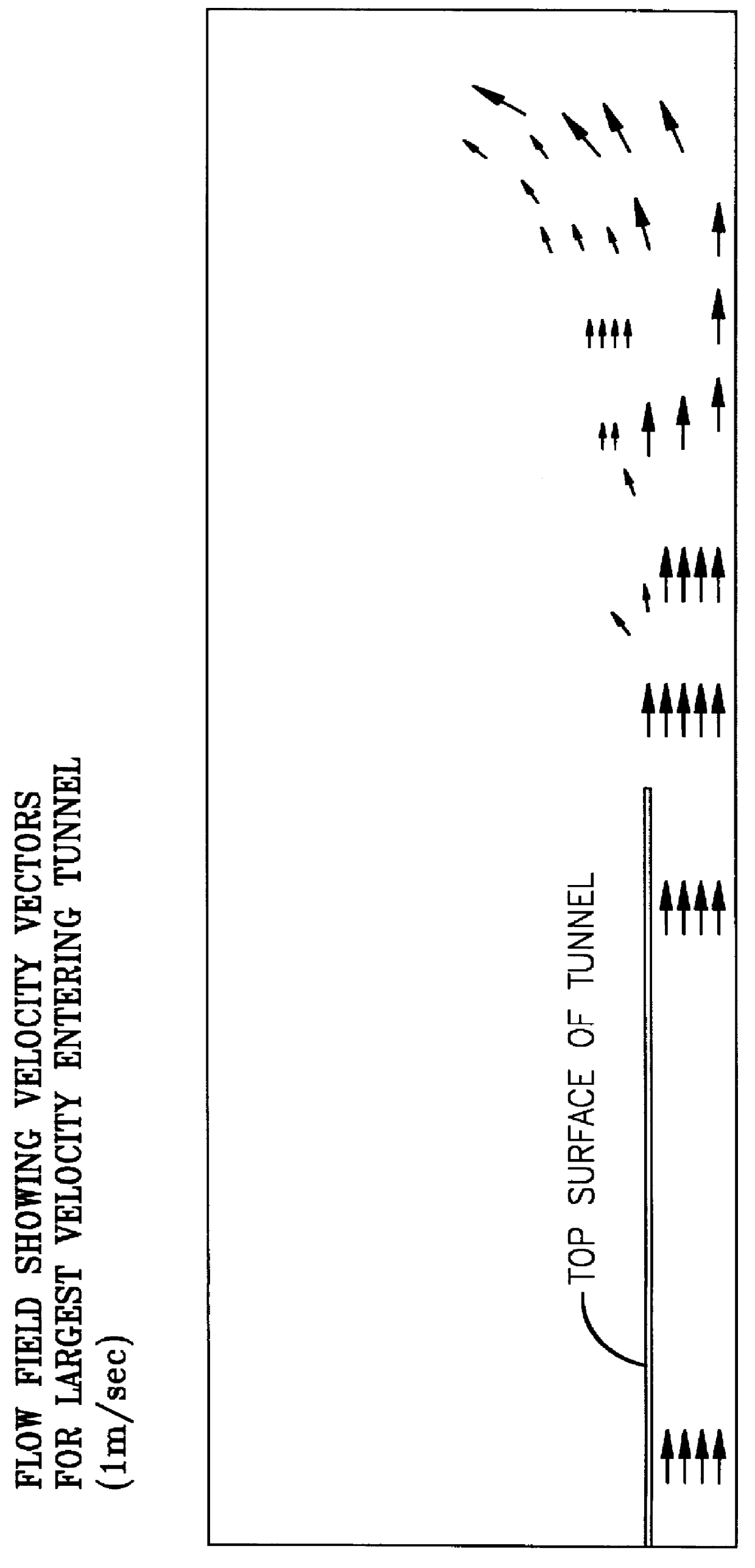
In embodiment 1, the difference in density between the gases inside and outside the temperature-controlled chamber was eliminated or minimized, so that buoyancy-driven flow patterns are eliminated or minimized. It is also possible to obtain benefit without the strategy of eliminating buoyancy-driven flow patterns. This next embodiment allows the continued use of pure nitrogen as the inertant, which probably is economically attractive. It achieves this by controlling the location of buoyancy-driven flow patterns so that the location of buoyancy-driven flow patterns is not the same as the location of the species boundary. In embodiment number 2, the arrangement of regions is a warm inert gas region, followed by a region of warm air chosen so that the density of the warm air essentially matches the density of the warm inert gas, followed by the atmosphere at ambient temperature. In embodiment number 2, warm nitrogen meets warm air of essentially equal density, creating no incentive for...

embodiment number 2

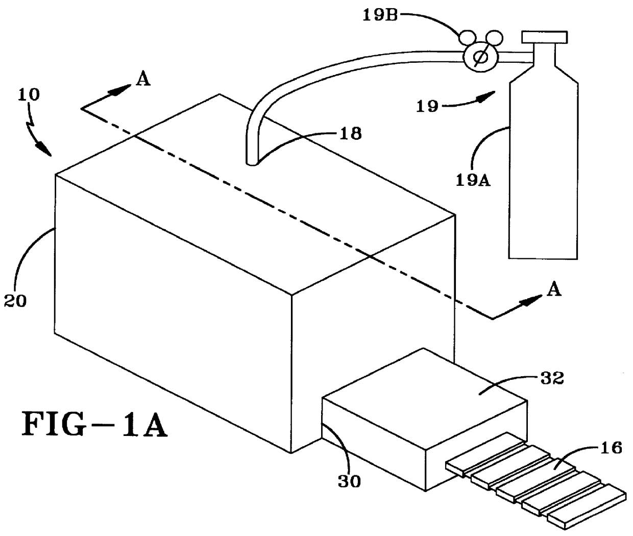
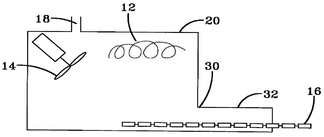
is shown in FIG. 6. By analogy with embodiment 1, it comprises temperature control chamber 110, enclosure 120, heater element 112 inside enclosure 120, fan 114 inside enclosure 120, and source of inert gas supply connection 118. There is also port 130 where tunnel 132 joins enclosure 120. Because the goal of this embodiment is to create a region of warm air next to the warm inert gas, it is helpful to place a local heater 136 somewhere in the vicinity of tunnel 132. Local heater 136 may be an electric resistive heater. It is preferably located near or at the bottom of tunnel 132 to guard against any possible thermal stratification such as was associated with the creeper in FIG. 2c especially. The bottom surface 134 of tunnel 132 may be porous so as to allow air to come up to local heater 136 from below by a chimney effect. However, the invention would also work if the bottom surface 134 were solid. The other surfaces of tunnel 132 are preferably solid. Bottom surface 134 may actuall...


PUM

PropertyMeasurementUnit
velocityaaaaaaaaaa
velocityaaaaaaaaaa
velocityaaaaaaaaaa

Abstract

A temperature-controlled chamber, such as an inerted oven for soldering, in which the buoyancy-induced motion of gas at the opening of the chamber is suppressed by adjusting the densities of gases. In one embodiment the inertant gas is chosen to be a mixture of inert gases such that the density of warm gas inside the oven approximately equals the density of the external atmosphere. In another embodiment, a buffer region of density-matched warm air is provided between the warm inertant inside the oven and the external atmosphere. The result is reduction in the consumption of inertant.

Description

The present invention relates to the field of temperature-controlled chambers, in which the gas inside the chamber must have a specific composition.There are various industrial processes which require exposing objects to a controlled non-ambient temperature while simultaneously maintaining a specific composition of the gas to which the objects are exposed while in the controlled-temperature zone. Commonly the controlled gas composition is oxygen-deficient so as to prevent oxidation or corrosion at the controlled temperature, particularly if the controlled temperature is hot. In many such processes there must be a continuous movement of objects into or out of the controlled-temperature zone, typically on a conveyor. This requires the presence of one or more openings (ports) in the boundary of the controlled-temperature chamber. Together, these features create conflicting requirements whereby the openings (ports) and the temperature difference between the chamber and the external atmo...

Claims


Application Information

Patent Timeline
Patent Type & Authority Patents(United States)
IPC IPC(8): B23K1/008F27D19/00F27B17/00F28D15/02F27D7/00F27D7/06F27D21/00F27D23/00F27D99/00
CPCB23K1/008F27B17/0016F27D7/06F27D19/00F28D15/02F27D21/0014F27D99/0075F27D2007/063
Inventor MATERNA, PETER A.
Owner MATERNA PETER A
Why Eureka
Try Eureka