X-ray radiography with highly charged ions

a radiography and x-ray technology, applied in the field of x-ray microscopy, vascular imaging, radiography with mammography, etc., can solve the problems of preventing the widespread use of radiography of mammography, limiting the diagnostic effectiveness of mammography, and limiting the concomitant cost of general medical us

Inactive Publication Date: 2000-09-05
LAWRENCE LIVERMORE NAT SECURITY LLC
View PDF10 Cites 42 Cited by
  • Summary
  • Abstract
  • Description
  • Claims
  • Application Information

AI Technical Summary

Problems solved by technology

The diagnostic effectiveness of mammography is limited by the difficulty of distinguishing abnormal features from the features of normal breast tissue.
Such sources have disadvantages that prevent their widespread use for radiography.
However, the present availability of synchrotron facilities, and concomitant cost thereof is far too limiting for general medical use.
Unfortunately, this is a dangerous procedure since it requires that a catheter be employed for injection of the contrast agent.
However, the image quality is seriously degraded with a venous injection of the contrast agent because the contrast agent is diluted by about 20:1 by the time it has gone through the lungs and both sides of the heart and starts to fill the coronary arteries.
Differential angiography has been demonstrated with synchrotron radiation, but such facilities are not available or suitable for general use.
However, the performance of such devices is presently limited by the characteristics of available x-ray sources.
In general, it is difficult to realize all the desired features of radiography at the same time.
For example, the use of a thicker and larger x-ray detection medium in order to achieve increased detection efficiency generally degrades the image resolution.
The use of energy filters with a conventional x-ray tube in order to narrow the energy spectrum of the x rays generally requires a higher power x-ray tube, and undesirable radiation at other energies leaks through the filters.
Such a broad spectrum does not allow suitable resolution or contrast of an image.

Method used


Image

  • X-ray radiography with highly charged ions
  • X-ray radiography with highly charged ions
  • X-ray radiography with highly charged ions

Examples


Embodiment Construction

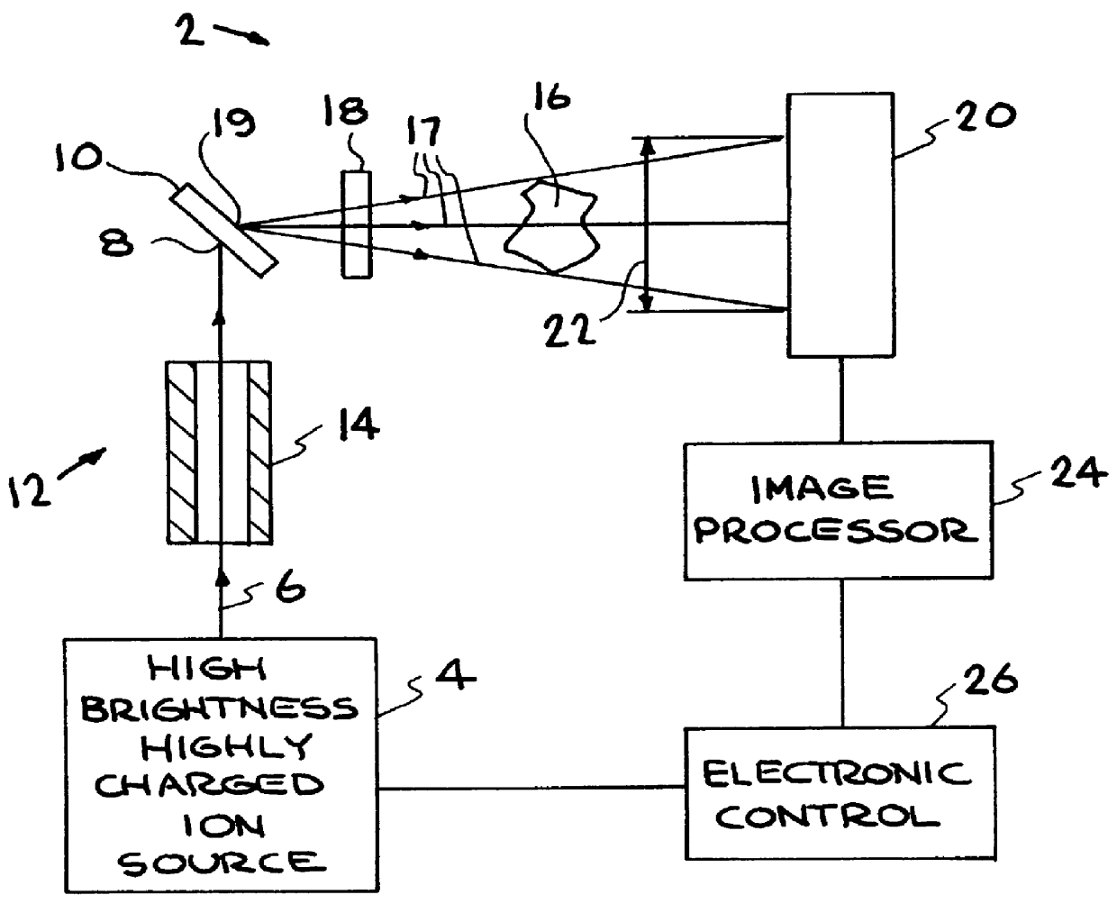
The following illustrates an x-ray microscope embodiment of the present invention.

Arrangement of the Microscope Embodiment

Referring to FIG. 1, the invention operates as a microscope when the size of the specimen and the distance of the specimen from the x-ray production target are both small The magnification is represented by M=b / a, where a is the distance from the x-ray source to a specimen and b is the distance from the x-ray source to the detector, e.g., a CCD. The magnification is easily adjusted by varying the position of the specimen. In this example a=5 mm, b=50 mm, and M=10. The principles of a projection x-ray imaging system also apply to the x-ray microscope described herein.

The resolution of a microscope or imaging system is ultimately limited by the wavelength of the radiation used to form an image. This limit is commonly referred to as the diffraction limit. In principle, the resolution of an x-ray microscope can be much better than the resolution of a visible-light mi...


PUM

PropertyMeasurementUnit
FWHMaaaaaaaaaa
sizeaaaaaaaaaa
sizeaaaaaaaaaa

Abstract

An extremely small (1-250 micron FWHM) beam of slow highly charged ions deexciting on an x-ray production target generates x-ray monochromatic radiation that is passed through a specimen and detected for imaging. The resolution of the x-ray radiograms is improved and such detection is achieved with relatively low dosages of radiation passing through the specimen. An apparatus containing an electron beam ion trap (and modifications thereof) equipped with a focusing column serves as a source of ions that generate radiation projected onto an image detector. Electronic and other detectors are able to detect an increased amount of radiation per pixel than achieved by previous methods and apparati.

Description

1. Field of the InventionThis invention relates generally to the field of radiography with mammography, vascular imaging, and x-ray microscopy being particular examples. More particularly, this invention relates to a new and improved method and apparatus for conducting internal biological imaging, industrial imaging, or microscopic imaging.2. Description of Related ArtMedical and industrial x-ray imaging typically use a conventional x-ray tube for x-ray production. The spectrum of x-ray energies emitted from an x-ray tube is very broad. However, a much narrower range of x-ray energies is advantageous for many applications. Typically, a conventional film or screen-film system is used for x-ray detection. In some applications, fluorescent screens are used to convert x-ray images to visible light that can be captured with a camera. A relatively new x-ray detection technique is the use of electronic x-ray imaging detectors to obtain digital images. The quality of an x-ray image and the ...

Claims


Application Information

Patent Timeline
Patent Type & Authority Patents(United States)
IPC IPC(8): G01N23/225G01N23/22G21K5/02H05G2/00A61B6/00
CPCA61B6/481A61B6/482A61B6/504G01N23/2257G21K5/02H05G2/00A61B6/4241A61B6/502A61B6/4092
Inventor MARRS, ROSCOE E.
Owner LAWRENCE LIVERMORE NAT SECURITY LLC
Why Eureka
Try Eureka