Gas detecting apparatus having condition monitoring means

a technology of condition monitoring and gas detection apparatus, which is applied in the field of electrochemical gas sensors, can solve the problems of time-consuming and undesirable, faults in such sensors, and broken signal wires or electrolyte loss

Inactive Publication Date: 2000-09-26
HONEYWELL ANALYTICS LTD
View PDF15 Cites 17 Cited by
  • Summary
  • Abstract
  • Description
  • Claims
  • Application Information

AI Technical Summary

Problems solved by technology

Hitherto, faults in such sensors, for example broken signal wires or loss of electrolyte, have been detected by applying a quantity of the gas to be detected to a sensor while monitoring the sensor output.
Staff are required to visit each sensor which is time consuming and undesirable if a sensor is located in a clean environment such as is found in semiconductor processing pla

Method used


Image

  • Gas detecting apparatus having condition monitoring means
  • Gas detecting apparatus having condition monitoring means
  • Gas detecting apparatus having condition monitoring means

Examples


Embodiment Construction

A preferred embodiment of the present invention will now be described, by way of example, with reference to the accompanying drawings.

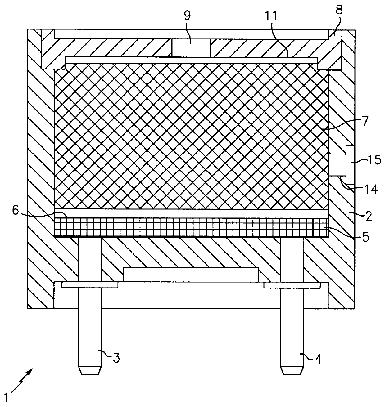
Referring to FIG. 1, an electrochemical sensor 1 comprises a generally cylindrical cup 2 formed from plastics resin material. First and second contact pins 3, 4 extend through the base of the cup 2. A layer 5 of potting compound is located immediately over the floor of the cup 2. A first electrode structure 6 overlays the potting compound. A wad 7, comprising a roll of glass fibre textile, sits on top of the first electrode structure 6. The wad 7 is soaked in an electrolyte. A disc-shaped cap 8 is dimensioned to plug the open end of the cup 2. The cap 8 has an axial, centrally located hole 9 to allow gas to be sensed to pass into the cup 2. A first wire (not shown) extends from the first contact pin 3 and overlays the first electrode structure 6. A second wire (not shown) extends from the second contact pin 4, up the inside of the cup 2, and between t...


PUM


Abstract

An operational amplifier (34) has its inverting input connected to a electrochemical gas sensor (38) for amplifying the current produced thereby in response to presence of a predetermined gas. In order to determine whether a sensor (38) is indeed present and that a sensor present is serviceable, a transient is applied to the non-inverting input of the operation amplifier (34). The presence or absence of the sensor (38) alters the transfer function of the operational amplifier (34) in respect of the test signal. If a serviceable sensor (38) is present, the gain of the operational amplifier (34) is high for the transient resulting at square pulse output. However, if a serviceable sensor (38) is not present, the gain of the operational amplifier (34) is relatively low and the transient retains its original form. Consequently the presence of a serviceable sensor (38) can be determined from the output of the operational amplifier (34) in response to the transient test signal.

Description

The present invention relates to self-testing gas detecting apparatus.BACKGROUND TO THE INVENTIONElectrochemical gas sensors typically comprise two or three electrodes separated by an electrolyte. These sensors generate currents in response to the presence of a gas, e.g. carbon monoxide hydrogen sulphide, sulphur dioxide, ammonia, for which they are adapted. Hitherto, faults in such sensors, for example broken signal wires or loss of electrolyte, have been detected by applying a quantity of the gas to be detected to a sensor while monitoring the sensor output. If a wire is broken or the electrolyte has leaked away, there will be no, or at least a reduced, output current.The need to test such sensors by applying quantities of gas has a number of disadvantages. Staff are required to visit each sensor which is time consuming and undesirable if a sensor is located in a clean environment such as is found in semiconductor processing plants. Also, if a sensor fails, its failure will not be...

Claims


Application Information

Patent Timeline
IPC IPC(8): G01N27/416
CPCG01N27/4163
Inventor LINDSAY, JOHN
Owner HONEYWELL ANALYTICS LTD
Why Eureka
Try Eureka