Thermal decomposition apparatus of reversed temperature gradient type for polymer waste

a technology of reverse temperature gradient and decomposition apparatus, which is applied in the field of apparatus, can solve the problems of large heating space, large amount of waste of heat, and uneconomical heat source of this type of apparatus, and achieve the effects of low cost, small size and simple structur

Inactive Publication Date: 2000-10-03
WADA YOUICHI
View PDF10 Cites 65 Cited by
  • Summary
  • Abstract
  • Description
  • Claims
  • Application Information

AI Technical Summary

Benefits of technology

An object of the present invention is to provide a thermal decomposition apparatus for polymer waste, which is simple in structure, small in size and inexpensive, and also operates in low cost.

Problems solved by technology

However, there is no detailed explanation in the publication as to the structure for directly connecting the tubular cracker and the extruder for introducing raw materials, and concerning this structure, the publication does not disclose measures for preventing an undesirable situation where the gas in the tubular cracker flows back to the extruder side or measures for eliminating a possibility of explosion being caused by air entering the tubular cracker from the extruder.
Although electric heat is easy to control and heat management is also easy, electric heat is an uneconomical heat source for this type of apparatus requiring a large quantity of heat.
However, the apparatus using the inclined pipe for thermal decomposition is constructed such that the inclined pipe extends through chambers (hot air spaces) for primary, secondary and tertiary thermal decompositions, each chamber occupying a large space, and thus an unnecessarily large heating space is required.
Accordingly, a considerably large quantity of heat is consumed uselessly, and since the hysteresis of temperature change is large, improvement is still needed as to the difficulty of heat management.
Also, the publication does not clearly set forth the relationship between the raw material melting tank and the inclined pipe for thermal decomposition with respect to an inflow of air and a backward flow of gas.
Thus, the technical idea disclosed in the publication is not satisfactory in view of reduction in size of the apparatus and reduction in the operating cost.

Method used


Image

  • Thermal decomposition apparatus of reversed temperature gradient type for polymer waste
  • Thermal decomposition apparatus of reversed temperature gradient type for polymer waste
  • Thermal decomposition apparatus of reversed temperature gradient type for polymer waste

Examples


Embodiment Construction

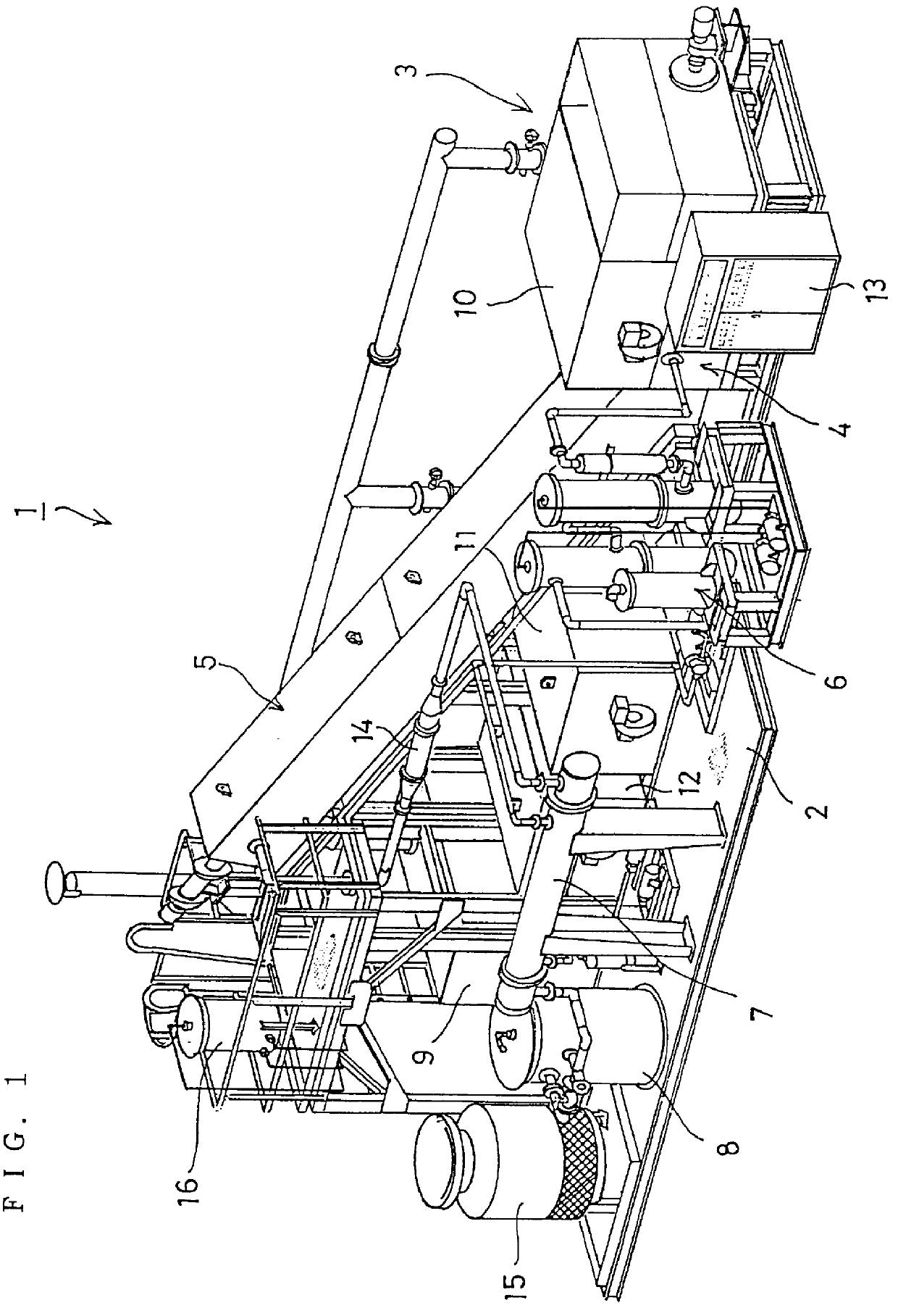
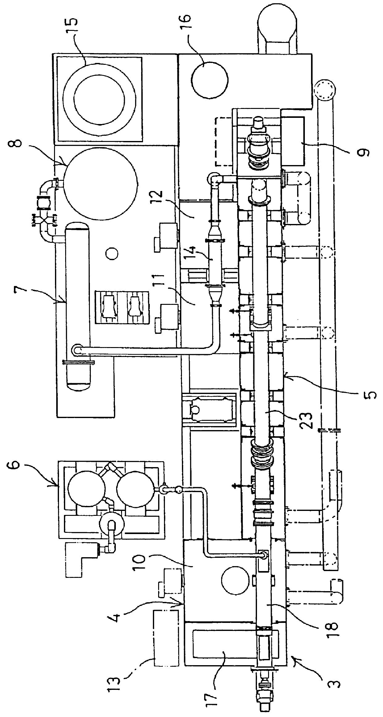
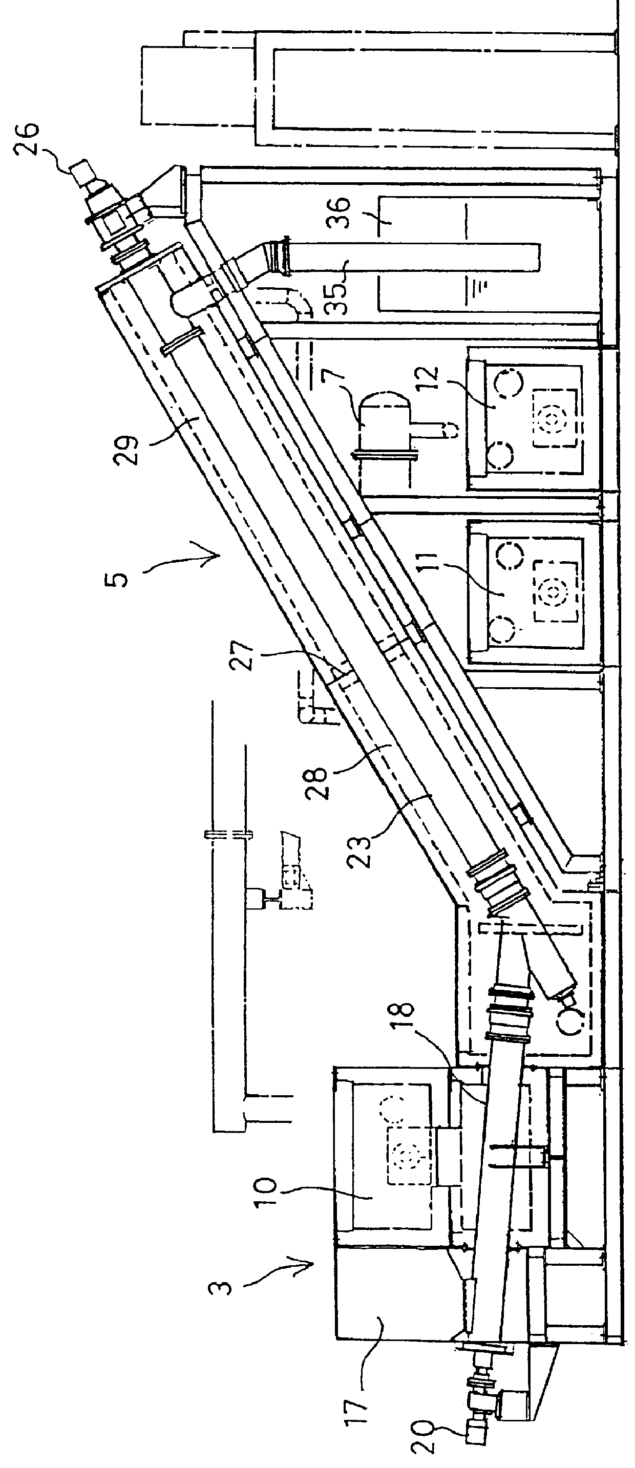
FIGS. 1 and 2 both illustrate an entire thermal decomposition apparatus according to a first embodiment, and FIG. 2 shows an internal arrangement of the apparatus with part of an introducing device and a decomposing device, which are described later, cut away. A thermal decomposition apparatus 1 comprises an introducing device 3, a fusing device 4, an inclined decomposition device 5, a dechlorinating device 6, a condenser 7, an oil storage tank 8, a sludge box 9, and first to third hot air generating furnace 10, 11 and 12 all set up on a base 2. Reference numeral 13 denotes a controller of ordinary type including an input / output section, a memory section, and an arithmetic processing section. The memory section stores therein programs for a thermal decomposition procedure, and the input section receives signals from various sensors arranged at respective suitable positions of the thermal decomposition apparatus 1. Reference numeral 14 denotes an accumulator connected to a pipe exten...


PUM

PropertyMeasurementUnit
temperatureaaaaaaaaaa

Abstract

A thermal decomposition apparatus for decomposing polymer waste is provided which is simple in structure, small in size and inexpensive, and also the operating cost thereof is low. A feed pipe 18 and an inclined pipe 23 are connected in the form of the letter V at a large angle therebetween, and a feed screw 19 and an feed-up screw 25 are arranged inside the respective pipes. Polymer waste introduced into a hopper 17 is melted in the interior of the feed pipe 18 by heat from a first hot air furnace 10 and accumulated in the V-shaped portion. The polymer melt is then conveyed upward by the feed-up screw 25. In the process of conveyance, the polymer melt undergoes primary decomposition by means of heat from a second hot air furnace 11 and the cracked gas thus generated undergoes secondary decomposition by the heat from a third hot air furnace 12, the resultant gas being guided to a condenser 7. Sludge drops down through a chute pipe 35 into a water tank 36.

Description

1. Field of the InventionThe present invention relates to an apparatus for decomposing waste of plastic products by heat to obtain useful fuel oil or gas.2. Related ArtThere have been proposed a large number of various apparatus for thermally decomposing waste of plastic products, i.e., polymer waste.Japanese Laid-Open Patent Publication No. 9-268293 entitled "Catalytic Cracking Apparatus for Synthetic Polymers and Oily Material Production Process Using the Apparatus" discloses a technical idea of providing the apparatus with a screw extruder, a tubular pre-heater and a tubular decomposing furnace, feeding polymer waste by the screw extruder and melting it with heat applied thereto, then feeding the polymer melt material to the tubular pre-heater or the tubular decomposing furnace to be further heated so that polymers may be thermally decomposed and gasified, and condensing the resultant gas (decomposed gas) to obtain oily material.The above publication also describes a structure th...

Claims


Application Information

Patent Timeline
Patent Type & Authority Patents(United States)
IPC IPC(8): C10B53/07C10B7/10C10B7/00B09B3/00C10G1/10
CPCC10B53/07C10B7/10Y02P20/143B09B3/00
Inventor WADA, YOUICHI
Owner WADA YOUICHI
Why Eureka
Try Eureka