Method and device for transporting cylindrical substrates to be coated

Inactive Publication Date: 2000-10-17
LEYBOLD SYST
View PDF19 Cites 32 Cited by
  • Summary
  • Abstract
  • Description
  • Claims
  • Application Information

AI Technical Summary

Benefits of technology

to provide a method of the type described above in which the coating of a large series of substrates having a multi-planar surface is mad

Problems solved by technology

For this purpose the coating chambers must be ventilated or again evacuated for the performance of the subsequent coating process,

Method used


Image

  • Method and device for transporting cylindrical substrates to be coated
  • Method and device for transporting cylindrical substrates to be coated
  • Method and device for transporting cylindrical substrates to be coated

Examples


Embodiment Construction

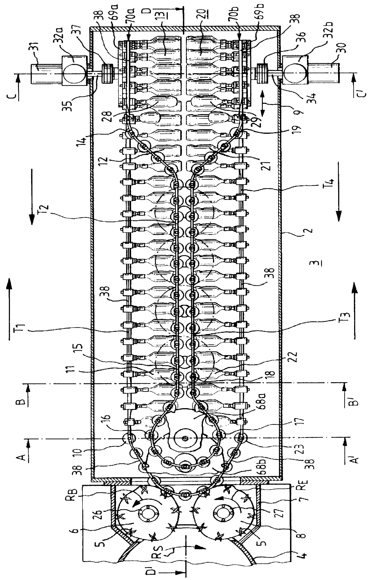
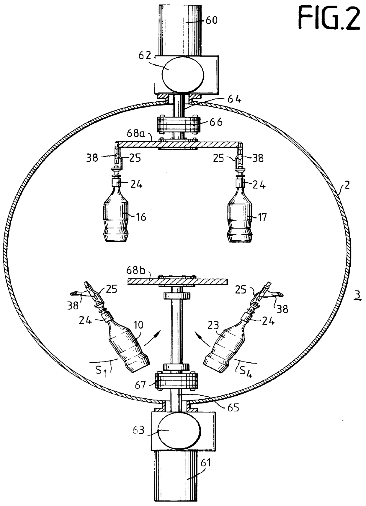
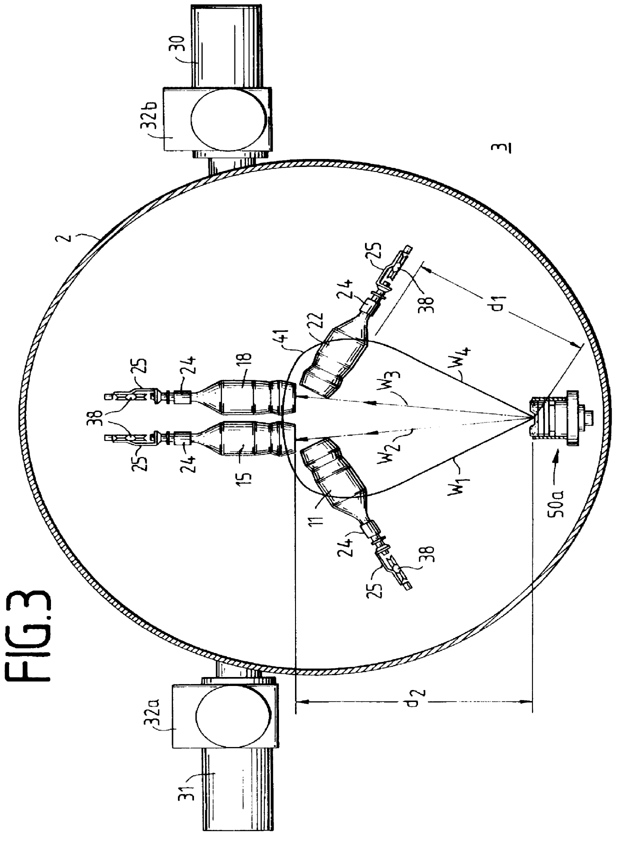
The present invention will now be described in further detail with reference to the drawings.

The coating device illustrated in FIG. 1 for coating cylindrical substrates 10-23,28,29 consists in essence of a coating chamber 2 and a transfer chamber 7 arranged at its upper end, through which the substrates to be coated 10-23,28,29 are transported via an air lock 4 into the coating chamber 2. The interior of the coating chamber 2 can be pumped down to a maximum negative pressure of 10.sup.-3 -10.sup.-6 typical of vacuum-supported coating processes by means of a conventional vacuum pump arrangement not shown in the drawings by way of vacuum connectors on the coating chamber. The pressure difference between the exterior 3, having a higher pressure, for instance, normal pressure, and the interior of the coating chamber 2 is maintained by way of the atmospherically sealing lock chamber 4. The substrates 10-23,28,29 to be coated are continuously supplied in the air lock 4 in, preferably indi...


PUM

PropertyMeasurementUnit
Transport propertiesaaaaaaaaaa
Cohesive energyaaaaaaaaaa

Abstract

For coating substrates (17,18,20,21,22) in a vacuum-coating chamber (2) the substrates are introduced by an air lock into the coating chamber (2) and moved along a transport path in front of the coating sources (50a,b,c,d) producing a coating cloud. To this end, the substrates (17,18,20,21,22) are led past the coating sources (50a,b,c,d) by means of holding devices (24) arranged movably on a transport belt (9) during at least two successive coating phases. During the one coating phase, the substrates (17,18,20,21,22) are oriented along one transport direction T3 oriented towards the coating sources (50a,b,c,d) such that essentially the substrate bottom of the cylindrical substrate is coated. During the subsequent second coating phase, the substrates are oriented in front of the coating sources (50a,b,c,d) in a direction T4 opposite the transport direction T3, wherein the substrates (17,18,20,21,22) are oriented such that essentially the cylindrical side surface is coated. By this method, the substrates (17,18,20,21,22) are coated successively in an identical manner and independently of possible substrate positions with relation to the coating sources (50a,b,c,d) during the coating process. Bottle-shaped containers, in particular, plastic bottles are vapor-coated with a gas- or fluid-barrier layer using the method. The coating sources (50a,b,c,d) include thermal vaporizers and/or plasma cathode sputter sources.

Description

INTRODUCTION AND BACKGROUNDThe present invention pertains to a method and a device for uniform coating of cylindrically shaped substrates with coating material that is deposited from a material cloud of material onto the substrates, wherein the substrates to be coated are brought into the environment of the material cloud.Coating methods of this general class are known, for instance, for the application of optically active layers onto optical elements. In these methods, the substrate to be coated is positioned inside a vacuum-coating chamber in front of a coating source. The material that forms the layer is emitted from the coating source as a material cloud is deposited on the surfaces of the substrate facing the coating source. In order, for instance, to coat the aforementioned optical glasses on both sides, it is necessary to interrupt the coating process, turn the substrates 180.degree. and then continue the coating process. In the customary methods, the coating process of multi...

Claims


Application Information

Patent Timeline
IPC IPC(8): C03C17/00C23C14/50C23C14/56B65G49/07B05B13/02
CPCC23C14/56C23C14/505
Inventor BAUMECKER, TOMASGRIMM, HELMUTHENRICH, JURGENMICHAEL, KLAUSRODLING, GERTULRICH, JURGEN
Owner LEYBOLD SYST
Why Eureka
Try Eureka