Radiation sensitive resin composition

a technology of radiofrequency and resin, applied in the direction of photosensitive materials, instruments, photomechanical equipment, etc., can solve the problems of nano-edge roughness, micro-fabrication problems, and difficulty in drawing such a minute pattern with high enough precision

Inactive Publication Date: 2000-10-24
JSR CORPORATIOON
View PDF13 Cites 84 Cited by
  • Summary
  • Abstract
  • Description
  • Claims
  • Application Information

AI Technical Summary

Benefits of technology

(A) (a) an alkali-insoluble or alkali low-soluble resin protected by an acid-decomposable group and turning alkali-soluble when said acid-decomposable group is decomposed or (b) an alkali-soluble resin and an alkali dissolution controller; and
(B) a photoacid generator comprising two or more chemical compounds, one being a compound which upon exposure to radiation generates a carboxylic acid having a boiling point of 150.degree. C. or higher under atmospheric pressure and the other a compound which upon exposure to radiation generates an acid other than a carboxylic acid (the resin composition described above is hereafter referred to as "positive tone resin composition").

Problems solved by technology

However, drawing such a minute pattern with high enough precision is very difficult with the conventional process based on visible rays (wavelength: 700-400 nm) or near ultraviolet rays (400-300 nm).
However, it has been pointed out that each of these chemically amplified resists has a peculiar drawback, giving rise to various obstacles for actual application to microfabrication, especially with a critical design dimension of 0.25 .mu.m or less.
In most recent years, reports have begun to appear on problems in microfabricating with a critical design dimension of approximately 0.20 .mu.m at a film thickness of 0.5 .mu.m or less.
These so-called "nano-edge roughness" or "coating surface roughness" problems are caused by excessive unevenness of the surface and the lateral faces of a resist after pattern formation, hampering microfabrication according to the designed critical dimension.
However, although such a composition excels in resolution, heat resistance, or etching endurance, it has insufficient performance particularly in the matter of "nano-edge roughness" or "coating surface roughness".

Method used


Image

  • Radiation sensitive resin composition

Examples


examples

Unless otherwise specified, all proportions are according to weight.

In the examples and comparative examples presented hereafter, measurement of Mw and Mw / Mn as well as evaluation of each resist are performed under procedures given below.

Resolution:

First, a resist coating built ona silicone wafer is exposed to different dosages of radiation, which is immediately followed by PEB, alkaline development, washing with water, and drying to form test resist patterns.

The resolution of a line-and-space pattern (1L1S) is defined as the smallest dimension (in .mu.m) of the resist pattern that can be resolved at an optimum exposure, which is the amount of radiation energy that can project a line-and-space pattern (1L1S) into a 1 to 1 width ratio at the design line width of 0.26 .mu.m.
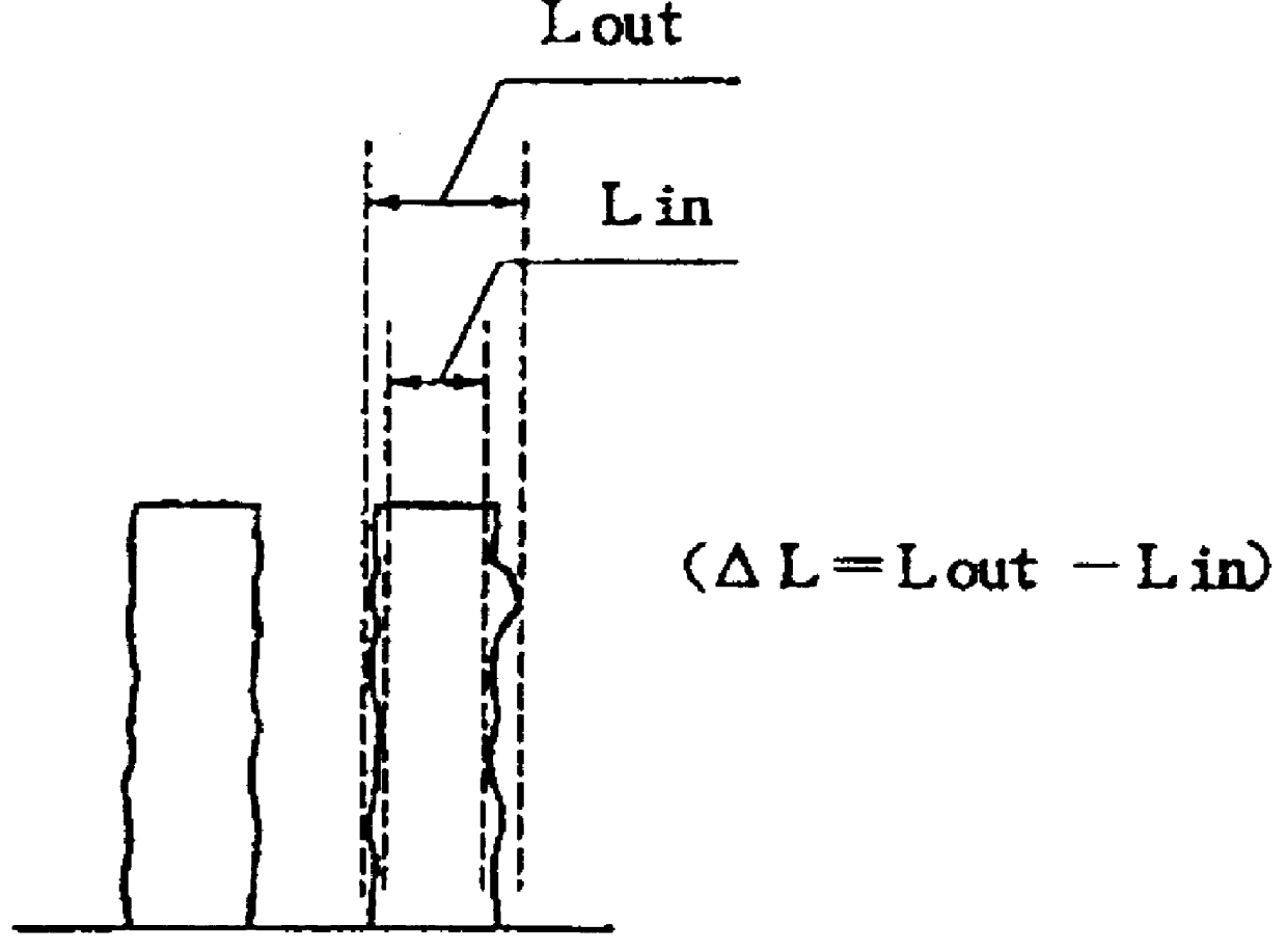
Pattern Profile:

Of a line-and-space pattern (1L1S) formed on a silicon wafer with a line width of 0.26 .mu.m, the lower end dimension La and the upper end dimension Lb of the square cross section of the pattern are...


PUM

PropertyMeasurementUnit
boiling pointaaaaaaaaaa
widthaaaaaaaaaa
wavelengthaaaaaaaaaa

Abstract

Positive as well as negative radiation sensitive resin compositions that, in addition to being capable of providing excellent resolution and pattern profile, are particularly excellent in avoiding the problems of "nano-edge roughness" or "coating surface roughness". The positive type radiation sensitive resin composition comprises (A) (a) an acid-decomposable group-containing resin, or (b) an alkali-soluble resin and an alkali dissolution controller, and (B) a photoacid generator comprising "a compound that upon exposure to radiation generates a carboxylic acid having a boiling point of 150.degree. C. or higher", and "a compound that upon exposure to radiation generates an acid other than a carboxylic acid". The negative type radiation sensitive resin composition comprises (C) an alkali-soluble resin, (D) a cross-linking agent, and the component (B) as described above.

Description

BACKGROUND OF THE INVENTION1. Field of the InventionThis invention relates to a radiation sensitive resin composition. More specifically, this invention relates to a radiation sensitive resin composition that is useful in the manufacture of positive and negative type resists suitable for microfabrication using various kinds of radiation. The composition contains a photoacid generator comprising a combination of a compound that generates a carboxylic acid upon exposure to radiation and another compound that generates another acid upon exposure to radiation.2. Description of Background ArtIn the field of microfabrication, as exemplified in the manufacture of an integrated circuit device, a rapidly progressing trend is to establish design rules for products with finer dimensions by the lithographic process with the aim of attaining higher degrees of circuit integration. Development of a lithographic process that is capable of reliably performing microfabrication with precision for a li...

Claims


Application Information

Patent Timeline
Patent Type & Authority Patents(United States)
IPC IPC(8): G03F7/004
CPCG03F7/004Y10S430/115Y10S430/122G03F7/0045G03F7/0382G03F7/0392G03F7/038G03F7/039G03F7/0397G03F7/091
Inventor KOBAYASHI, EIICHISHIMIZU, MAKOTOTANABE, TAKAYOSHIIWANAGA, SHIN-ICHIRO
Owner JSR CORPORATIOON
Why Eureka
Try Eureka