Method of making an ink jet printhead filter by laser ablation

Inactive Publication Date: 2000-10-31
XEROX CORP
View PDF13 Cites 87 Cited by
  • Summary
  • Abstract
  • Description
  • Claims
  • Application Information

AI Technical Summary

Benefits of technology

1) prevent particulate matter of a size sufficient to block channels from entering the printhead channels;
2) improve ink droplet directionality in an ink jet printhead.
3) having increased strength to enable

Problems solved by technology

This technique has the disadvantage of flow restriction due to the proximity to single channels and poor yields due to defects near single channels.
Electroformed screen filters having pore size which is small enough to filter out particles of interest result in filters which are very thin and subject to breakage during handling or wash steps.
Also, the preferred nic

Method used


Image

  • Method of making an ink jet printhead filter by laser ablation
  • Method of making an ink jet printhead filter by laser ablation
  • Method of making an ink jet printhead filter by laser ablation

Examples


first embodiment

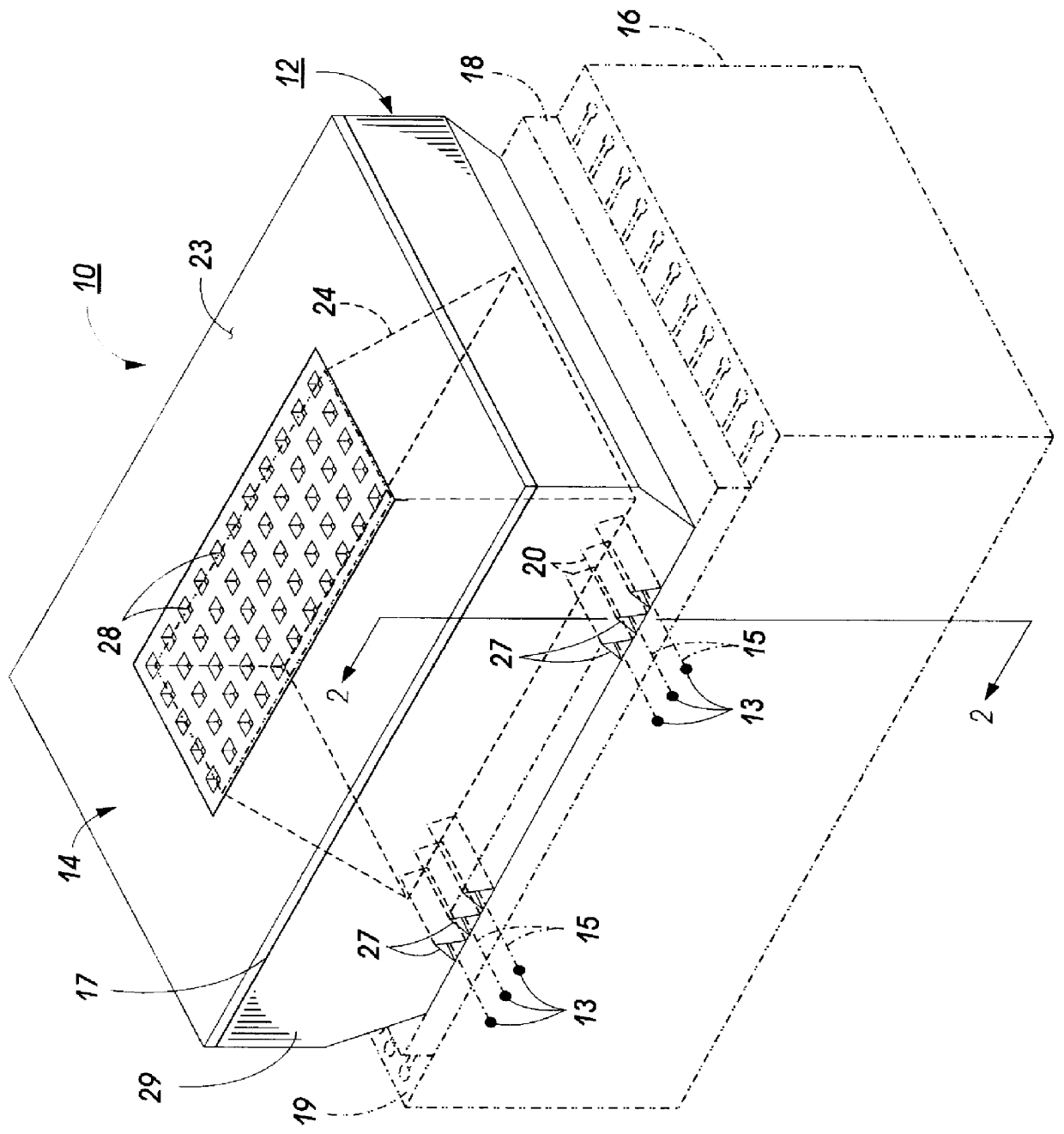
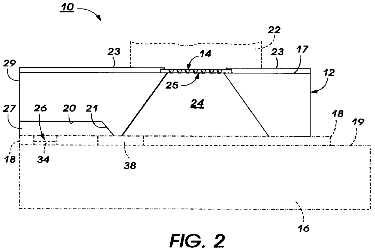
Filter 14 of the present invention has been fabricated, in a first embodiment, and as discussed below, by laser-ablating holes 28 through a thin polymer film to form a fine filter and then adhesively bonding the filter to the fill hole side 17 of channel plate 12 by, for example, the adhesive transfer method disclosed in U.S. Pat. No. 4,678,529, whose contents are hereby incorporated by reference.

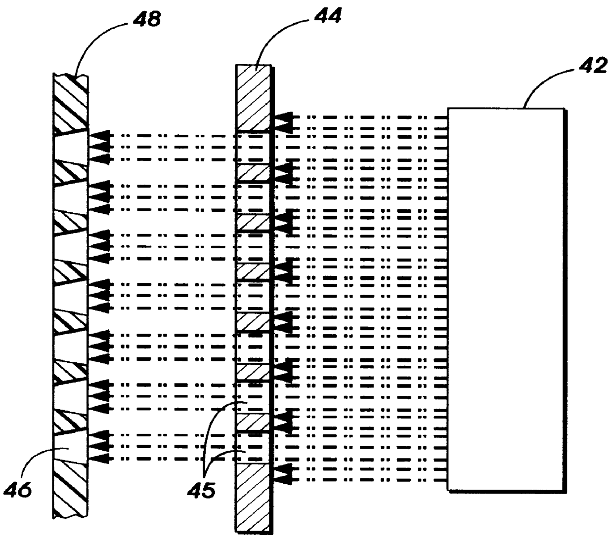
Referring to FIG. 3, large diameter output beams are generated by excimer laser 42 and directed to a mask 44 having a plurality of holes 45, with total area sufficient to cover the ink inlet 25. The holes can be closely packed with diameters as small as 2.5 microns. The radiation passing through the mask 44 forms a plurality of tapered holes 46 in polymer film 48 which, in a preferred embodiment, is KAPTON.RTM., or other polymer films which have been selected for chemical compatibility with the inks to be used. Ablated film 48 has thus been fabricated into filter 14 which can then be aligne...

second embodiment

In a second embodiment, shown in FIGS. 4, 5, a tape seal 50 is used to seal the cartridge manifold to the ink inlet. Seal 50 is ablated by the above-described process to form the filter 14', as well as the outline of the seal. The tape seal is then aligned with inlet 25 and bonded to the top surface of channel plate 12.

third embodiment

In a third embodiment, shown in FIG. 6, polymer film 48' is first laminated to channel plate 12 and the wafer is diced into separate printheads. Each printhead is then positioned so that the channel plate top surface is aligned with the desired masking radiation pattern to fabricate filter 14.


PUM

PropertyMeasurementUnit
Diameteraaaaaaaaaa
Sizeaaaaaaaaaa
Strengthaaaaaaaaaa

Abstract

A method for fabricating a filter element to prevent contaminants from entering an ink supply inlet of an ink jet printhead. The filter is formed by laser ablation process in which output laser radiation is directed through a mask system or light transmitting system to create a filter hole pattern in a thin film. Slightly tapered holes are formed in the film, and the formed filter element is laminated to the ink supply inlet. The tapered holes provide improved flow/impedance and add increased structural strength.

Description

BACKGROUND OF THE INVENTION AND MATERIAL DISCLOSURE STATEMENTThe invention relates to ink jet printers and, more particularly, to a thermal ink jet printhead having a filter over its ink inlet and a laser ablation fabrication process for forming the filter.A typical thermally actuated drop-on-demand ink jet printing system uses thermal energy pulses to produce vapor bubbles in an ink-filled channel that expels droplets from the channel orifices of the printing system's printhead. Such printheads have one or more ink-filled channels communicating at one end with a relatively small ink supply chamber (or reservoir) and having an orifice at the opposite end, also referred to as the nozzle. A thermal energy generator, usually a resistor, is located within the channels near the nozzle at a predetermined distance upstream therefrom. The resistors are individually addressed with a current pulse to momentarily vaporize the ink and form a bubble which expels an ink droplet. A meniscus is for...

Claims


Application Information

Patent Timeline
IPC IPC(8): B41J2/175B41J2/14B41J2/16B41J2/05
CPCB41J2/14145B41J2/17563Y10T156/1056Y10T156/1062B41J2002/14403Y10T83/0524
Inventor MARKHAM, ROGER G.ANDREWS, JOHN R.KNEEZEL, GARY A.
Owner XEROX CORP
Why Eureka
Try Eureka