Shallow trench isolation (STI) with bilayer of oxide-nitride for VLSI applications

a technology of oxide-nitride and thin trench isolation, which is applied in the manufacture of semiconductor/solid-state devices, basic electric elements, electric devices, etc., can solve the problems of nitride liner to active silicon sidewalls posing serious limitations the nitride liner to active silicon sidewalls posing a serious limitation in the amount of thermal oxide,

Inactive Publication Date: 2000-10-31
QIMONDA +1
View PDF12 Cites 68 Cited by
  • Summary
  • Abstract
  • Description
  • Claims
  • Application Information

AI Technical Summary

Benefits of technology

Preferably, the insulating layer comprises tetraethylorthosilicate deposited at a low pressure of about 200 mTorr to 1 Torr having a thickness of about 50 to 300 .ANG.. Preferably, the thermal oxide has a thickness of about 100 .ANG. and the silicon nitride liner has a thickness of about 55 .ANG.. The method may further include, prior to step (e), the step of high temperature annealing the thermal oxide and the insulating layer.
In still yet another aspect, the present invention is directed to a semiconductor device comprising a semiconductor substrate having one or more electrical devices formed thereon; a plurality of shallow trench isolations formed on the substrate to isolate the electrical devices, the isolations having a thermal oxide grown in the trench; a layer of tetraethylorthosilicate over the thermal ox...

Problems solved by technology

However, one drawback of the nitride liner presently used in the STI is its effect in trapping charge.
The proximity of the nitride liner to the active silicon sidewalls poses a serious limitation in the amount of thermal oxide that is initially grown in the STI (to heal etching-related damage).
This ...

Method used


Image

  • Shallow trench isolation (STI) with bilayer of oxide-nitride for VLSI applications
  • Shallow trench isolation (STI) with bilayer of oxide-nitride for VLSI applications
  • Shallow trench isolation (STI) with bilayer of oxide-nitride for VLSI applications

Examples


Embodiment Construction

)

In describing the preferred embodiment of the present invention, reference will be made herein to FIGS. 1-6 of the drawings in which like numerals refer to like features of the invention. Features of the invention are not necessarily shown to scale in the drawings.

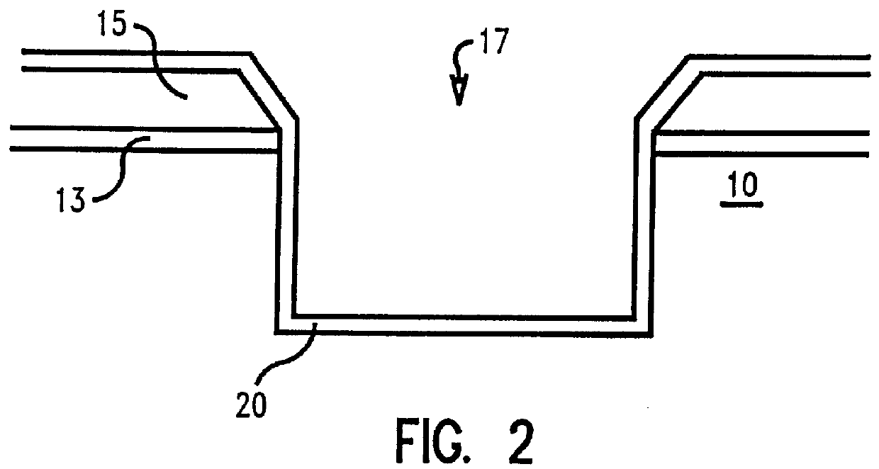
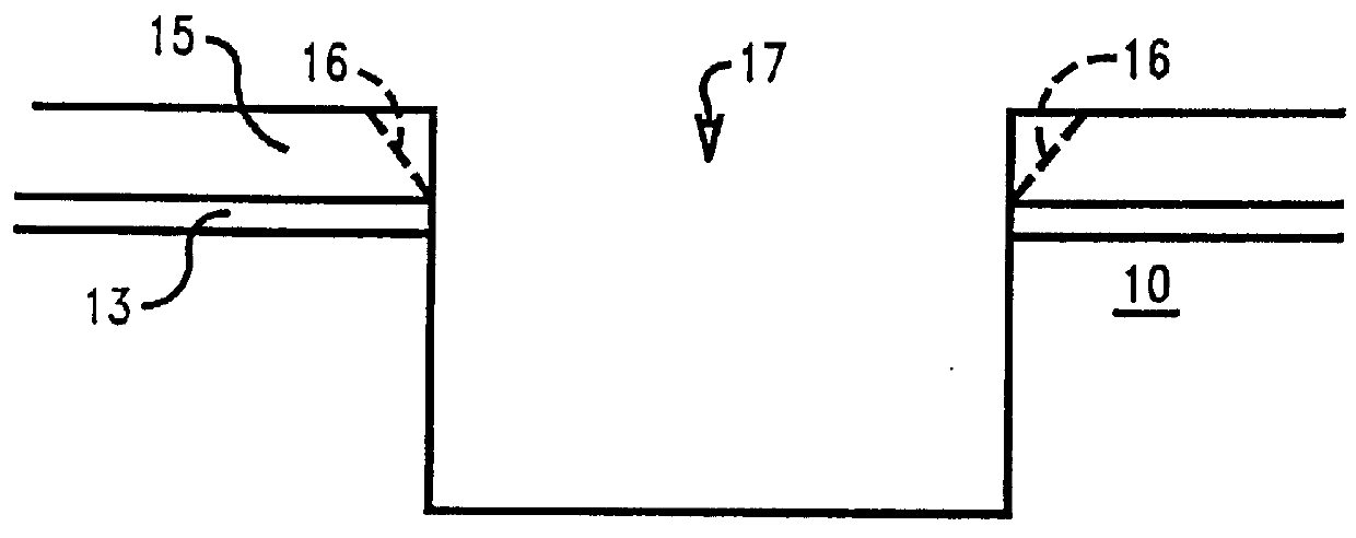
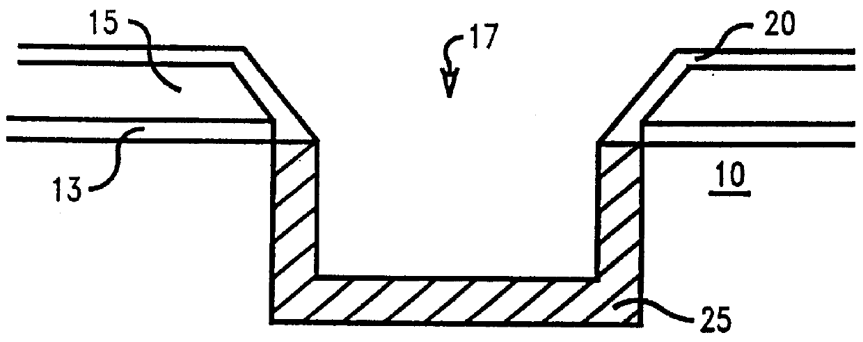
FIGS. 1 to 4 show a first preferred embodiment of the present invention. In FIG. 1, a semiconductor substrate 10 has a pad dielectric layer deposited thereon comprising a pad oxide layer 13, preferably silicon oxide, and a pad nitride layer 15, preferably silicon nitride. The pad dielectric layer on the silicon substrate is patterned and etched according to know processes in the art, preferably a dry etch process, to form a shallow trench isolation via 17 approximately 0.25 .mu.m deep. Pad nitride layer 15 includes portions 16 forming the upper corners adjacent to via 17. After the etching process, the isolation vias are wet cleaned using a mixture of dilute hydrofluoric acid (DHF), sulfuric peroxide, Huang A (H.sub.2 O.s...


PUM


Abstract

A reduction in parasitic leakages of shallow trench isolation vias is disclosed wherein the distance between the silicon nitride liner and the active silicon sidewalls is increased by depositing an insulating oxide layer prior to deposition of the silicon nitride liner. Preferably, the insulating oxide layer comprises tetraethylorthosilicate. The method comprises of etching one or more shallow trench isolations into a semiconductor wafer; depositing an insulating oxide layer into the trench; growing a thermal oxide in the trench; and depositing a silicon nitride liner in the trench. The thermal oxide may be grown prior to or after deposition of the insulating oxide layer.

Description

1. Field of the InventionThis invention relates to the manufacture of semiconductor devices, in particular, dynamic random access memories (DRAMs) having shallow trench isolation (STI) vias for isolating the various transistors present within a capacitor array.2. Description of Related ArtThe use of silicon nitride (Si.sub.3 N.sub.4) liners in shallow trench isolations (STIs) have proven to be vital for eliminating silicon defects in trench-based DRAM at 0.25 .mu.m groundrules. With shrinking dimensions envisioned for the Gigabit generations, it is argued that a nitride liner, which can effectively block oxygen from penetrating into the trench storage capacitor, is a necessity. However, one drawback of the nitride liner presently used in the STI is its effect in trapping charge. Since the nitride liner sits close to the active silicon sidewalls, it has been shown to exacerbate (1) STI-bounded perimeter leakage, (2) node to P-well junction leakage, and most importantly, (3) buried P-...

Claims


Application Information

Patent Timeline
IPC IPC(8): H01L21/70H01L21/762H01L21/76
CPCH01L21/76224H01L21/76
Inventor AGAHI, FARIDBRONNER, GARYFLIETNER, BERTRANDHAMMERL, ERWINHO, HERBERTSRINIVASAN, RADHIKA
Owner QIMONDA
Why Eureka
Try Eureka