Laminated ink-jet recording head, a process for production thereof and a printer equipped with the recording head

a technology of inkjet recording head and printing process, which is applied in the direction of printing, electrical equipment, and electromechanical/electrostrictive/magnetostrictive devices, etc., can solve the problem that the voltage necessary to issue ink may potentially exceed the voltage of the piezoelectric vibrating elemen

Inactive Publication Date: 2000-12-12
SEIKO EPSON CORP
View PDF11 Cites 32 Cited by
  • Summary
  • Abstract
  • Description
  • Claims
  • Application Information

AI Technical Summary

Benefits of technology

In addition, the aforementioned titanium layer may be formed such that the portion formed in the region corresponding to the pressure generating chamber has a smaller film thickness than the portion formed in the other region. By so doing, ink can be efficiently issued from the pressure generating chamber.
If the film thickness of the titanium layer is less than a tenth or more than twice the film thickness of the aforementioned piezoelectric vibrating element, the rigidity of the titanium layer prevents efficient issuance of the ink.

Problems solved by technology

If the film thickness of the aforementioned piezoelectric vibrating element is less than 1 .mu.m, the voltage necessary to issue the ink may potentially exceed the withstand voltage of the piezoelectric vibrating element.

Method used


Image

  • Laminated ink-jet recording head, a process for production thereof and a printer equipped with the recording head
  • Laminated ink-jet recording head, a process for production thereof and a printer equipped with the recording head
  • Laminated ink-jet recording head, a process for production thereof and a printer equipped with the recording head

Examples


first embodiment

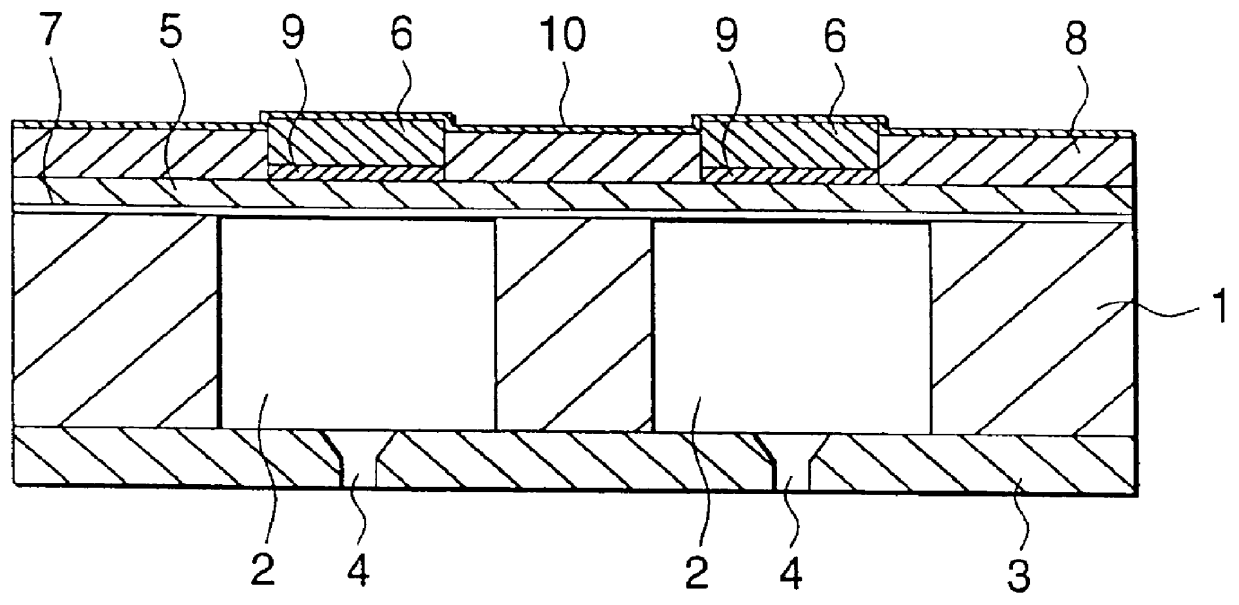
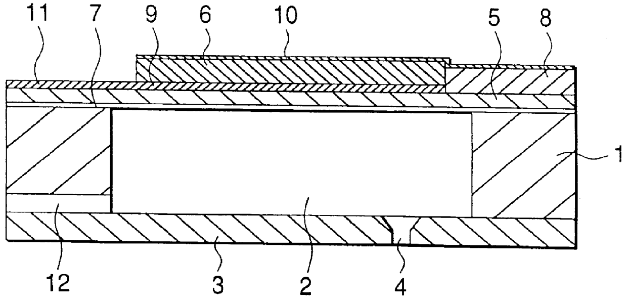
FIGS. 1(a) and (b) and FIG. 2 each show a first embodiment of the invention and in these drawings, numeral 1 signifies a spacer. The spacer is either made by performing anisotropic etching or chemical etching on a substrate, such as a single-crystal silicon substrate, a stainless steel substrate or the like, that have a film thickness (thickness) suitable for forming pressure generating chambers 2 in such a way that it is penetrated from one side to the other (from top to bottom or from bottom to top as seen in FIG. 1(a)) or by press forming a ceramic green sheet and sintering it.

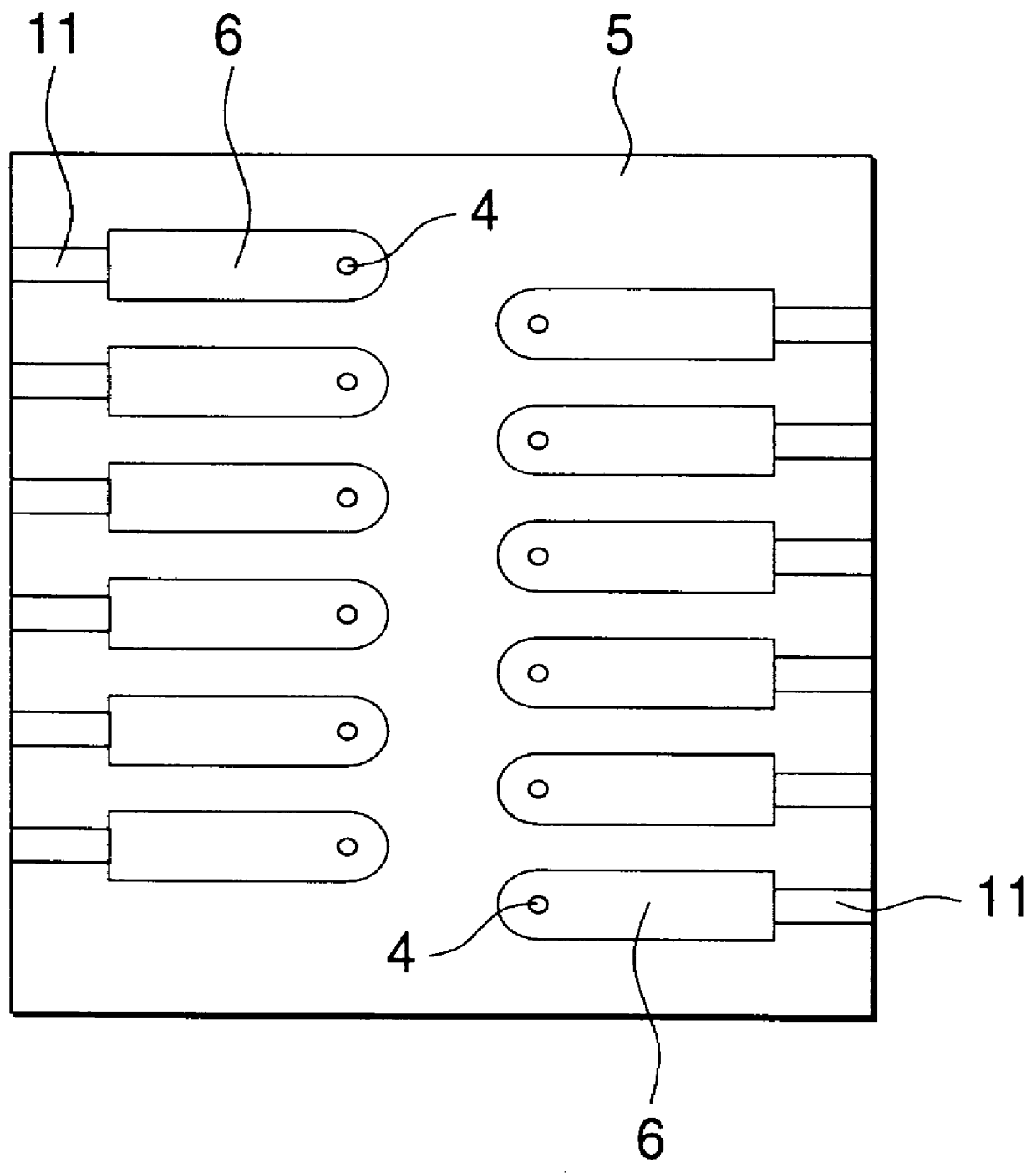
Numeral 3 signifies a nozzle plate. Nozzle orifices 4 are bored through the plate in positions that correspond to (communicate with) the pressure generating chambers 2. The plate is secured to one side of the spacer 1 by means of an adhesive or the like so as to provide an airtight condition.

Numeral 5 signifies a diaphragm that is made of a thin sheet elastic enough to be capable of being deformed by the fl...

second embodiment

We next describe a second embodiment of the invention in accordance with the process shown in FIGS. 5(a)-5(c) and 6(a)-6(c). In this embodiment, description is made of the case where the spacer is formed of a single-crystal silicon substrate that can be etched anisotropically.

In the step shown in FIG. 5(a), all surfaces of a single-crystal silicon substrate 40 are treated by a thermal oxidation method to form a silicon dioxide film 41. The silicon dioxide film 41 also functions as an etching protective film in a subsequent step.

Next, in the step shown in FIG. 5(b), an insulation film 43 is formed on the silicon single-crystal substrate 40 having the silicon dioxide film 41 formed thereon, in such a way that it has openings (windows) 42 in positions that correspond to pressure generating chambers 50.

Next, in the step shown in FIG. 5(c), a titanium layer 44 is formed on the surface of the silicon dioxide film 41 via the openings (windows) 42 formed in the step shown in FIG. 5(b). In o...

third embodiment

We next describe a third embodiment of the invention with reference to FIGS. 8(a) and 8(b).

In the drawings, numeral 61 signifies a titanium layer serving as a common lower electrode and this titanium layer 61 is formed in a film thickness of about 0.1 .mu.m by sputtering titanium on the entire surface of a diaphragm 62. Numeral 63 signifies an insulation layer formed on the surface of the diaphragm 62 and this insulation layer 63 is formed of an insulation material such as silicon dioxide (SiO.sub.2), polyimide or the like in a film thickness of about 1 .mu.m in such a way as to form openings (windows) in regions that correspond to pressure generating chambers 2.

Numeral 64 signifies a piezoelectric vibrating element, which is formed by growing a piezoelectric material on the titanium layer 61 serving as a substrate for growth by the hydrothermal method in such a film thickness (thickness) that its surface protrudes beyond the insulation layer 63. Numeral 65 signifies discrete electr...


PUM

PropertyMeasurementUnit
thicknessaaaaaaaaaa
thicknessaaaaaaaaaa
thicknessaaaaaaaaaa

Abstract

PCT No. PCT/JP96/01924 Sec. 371 Date May 14, 1997 Sec. 102(e) Date May 14, 1997 PCT Filed Jul. 11, 1996 PCT Pub. No. WO97/03834 PCT Pub. Date Feb. 6, 1997A laminated ink-jet recording head is provided that has a strong joint between the diaphragm and the piezoelectric vibrating element and which can be driven on low voltage. The recording head is of such a design that a lower electrode is provided on the diaphragm in at lest a region that corresponds to said pressure generating chamber, the lower electrode being overlaid with the piezoelectric vibrating element formed by a hydrothermal method, said piezoelectric vibrating element in turn being overlaid with an upper electrode and having a film thickness of not less than 1 mu m but not more than 10 mu m. The invention further provides a process for producing this recording head, as well as an apparatus such as a printer that is equipped with this recording head.

Description

This invention relates to a laminated ink-jet recording head, a process for making the head and an apparatus such as a printer having the recording head; in particular, the invention relates to a laminated ink-jet recording head or the like that comprise a nozzle plate, pressure generating members and a diaphragm in superposition and which have piezoelectric vibrators of a flexural vibrating mode mounted on a surface of the diaphragm.Laminated ink-jet recording heads have heretofore been known that comprise a nozzle plate, pressure generating compartments and a diaphragm in superposition and which have piezoelectric vibrators of a flexural vibrating mode mounted on a surface of the diaphragm (for example, Unexamined Published Japanese Patent Application (kohyo) No. Hei 5-504740). Typically, most of the members that constitute the laminated ink-jet recording head are formed of ceramics. Hence, by sintering the aforementioned members in the form of superposed green sheets (claey sheet...

Claims


Application Information

Patent Timeline
Patent Type & Authority Patents(United States)
IPC IPC(8): B41J2/14B41J2/16H01L41/24B41J2/135B41J2/145B41J2/155
CPCB41J2/14233B41J2/1623B41J2/1625B41J2/1629B41J2/1631B41J2/1632B41J2/1646H01L41/319B41J2/161Y10T29/49155B41J2002/1425B41J2002/14387B41J2202/03H01L41/314Y10T29/42Y10T29/49401H10N30/077H10N30/081H10N30/079
Inventor USUI, MINORUSHIMADA, MASATOMURAI, MASAMISUMI, KOUJINISHIWAKI, TSUTOMU
Owner SEIKO EPSON CORP
Why Eureka
Try Eureka