Cavity-backed slot antenna

a slot antenna and cavity technology, applied in the direction of resonant antennas, radiating element structures, radiating element housings, etc., can solve the problems of antenna back-scatter, transmission line components, antenna back-scatter tends to be large, and generally unacceptable, so as to increase capacitance

Inactive Publication Date: 2000-12-12
L 3 COMM CORP
View PDF9 Cites 56 Cited by
  • Summary
  • Abstract
  • Description
  • Claims
  • Application Information

AI Technical Summary

Benefits of technology

One solution to this problem is to recess a patch or cavity-backed slot antenna slightly below the surrounding surface. The resulting cavity is filled with a layer of closed cell foam, or some other material with a very low dielectric constant, and then a layer of magnetic radar absorbing material (RAM) is placed on top of the foam. The RAM is brought flush with the surrounding surface, and its edges are usually tapered to provide a gradual transition to the surrounding metallic surface. In the operating band of the antenna the RAM is designed to be somewhat transparent with resulting losses usually not exceeding two or three dB. At higher frequencies the RAM is designed to be much more absorptive so that the antenna, and its back-scatter at higher order resonances, are hidden by the RAM cover material. The use of RAM for back-scatter suppression makes the design relatively large, complex and costly. It is very difficult to obtain a sufficiently sharp frequency cut-off in the RPM to avoid compromising either the radiation efficiency or the back-scatter suppression.

Problems solved by technology

In the design of aircraft and other vehicles with low radar cross section, the back-scatter from antennas is an important issue.
Often the problem is to design antennas that function efficiently over a relatively narrow bandwidth but suppress the back-scatter at frequencies outside this band.
The problem is that the patch, like other transmission line components, does not resonate at a single frequency.
At these higher frequencies, antenna back-scatter tends to be large and generally unacceptable.
The use of RAM for back-scatter suppression makes the design relatively large, complex and costly.
It is very difficult to obtain a sufficiently sharp frequency cut-off in the RPM to avoid compromising either the radiation efficiency or the back-scatter suppression.
While this susceptance works well in combination with the susceptance of the patch to form the primary resonance, the larger values of susceptance at higher frequencies tend to short out the higher order resonances.
Nevertheless, ceramics are difficult to work with in development, and their dielectric constant varies significantly from lot to lot.
Soft substrates with ceramic loading can also be used for this application, but the control of the dielectric constant is even more of a problem.
Both materials tend to be relatively costly.

Method used


Image

  • Cavity-backed slot antenna
  • Cavity-backed slot antenna
  • Cavity-backed slot antenna

Examples


Embodiment Construction

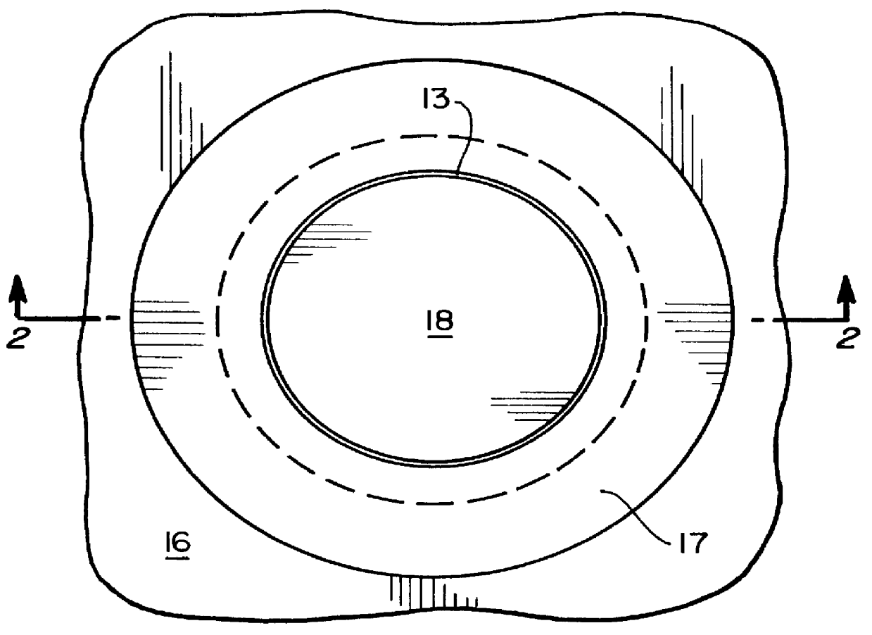
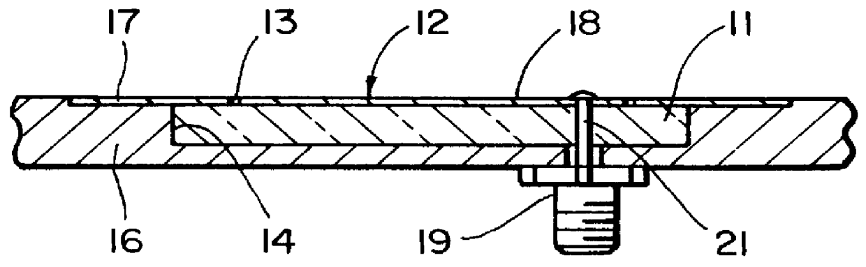
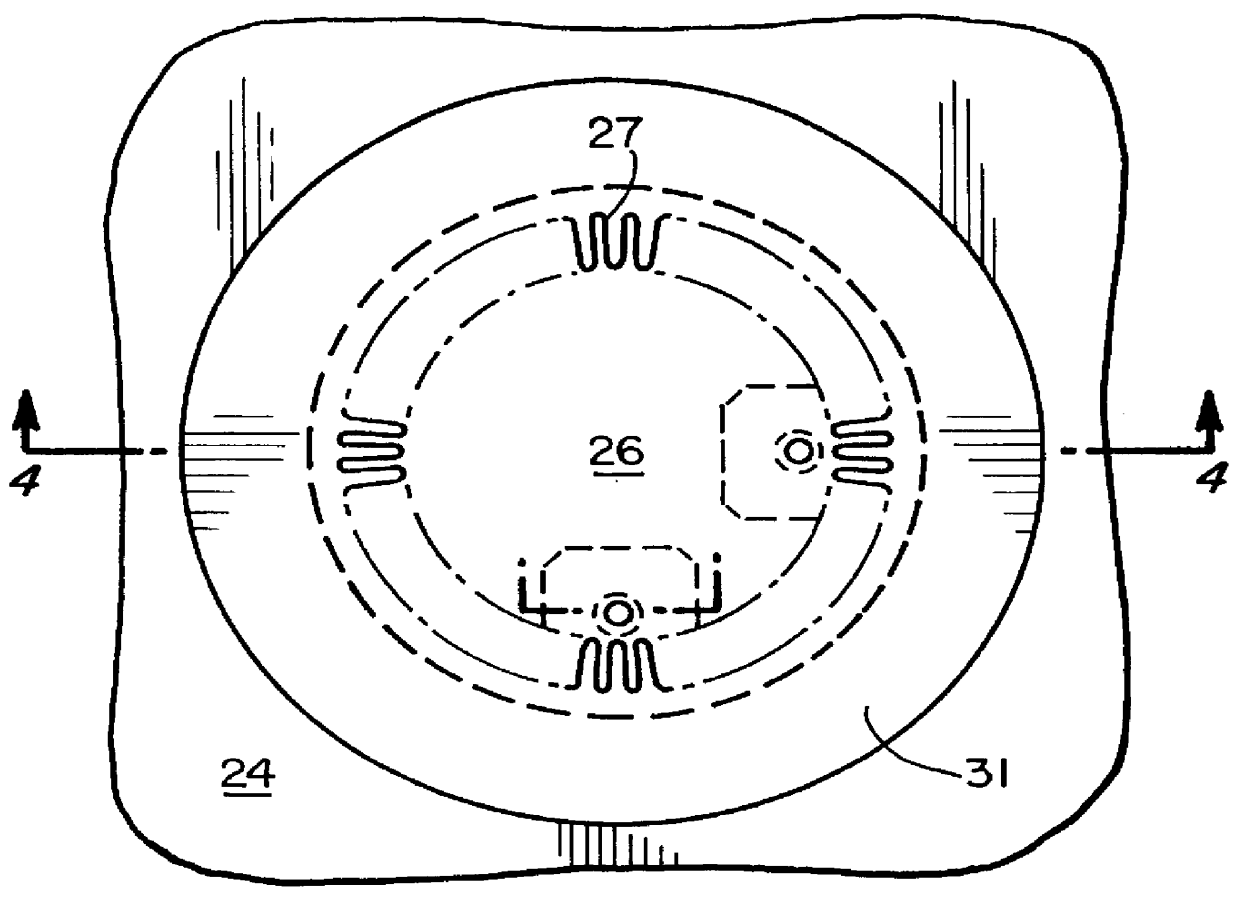
Referring to FIGS. 3-5 a slot antenna including increased capacitance per unit length of the radiating portion of the patch is shown. The antenna is formed over a cavity 23 formed in a conductive structure 24 which serves as the ground plane. The patch antenna 26 is defined by etching a meander slot 27 in the conductive film 28, such as copper, carried by a thin dielectric substrate 29. The capacitance is increased per unit length of the slot in a direction perpendicular to the E fields. The outer or surrounding film 31 is connected to the ground plane or structure whereby when voltages are applied to the film via the coaxial connectors 32 and 33, electric fields are set up across the slot and radiate electromagnetic energy omnidirectionally. The cavity is preferably filled with a foam material 34. In one example the slot was 0.0075 inches wide, with a meander length of 0.12 inches, and a meander repetition rate of 28.65 per radian, formed in a copper film 0.001 inches thick, carrie...


PUM


Abstract

A cavity backed slot antenna comprises a conductive cavity, a conductive film carried by a thin dielectric substrate which is above the cavity. The conductive film includes one or more slots which an electric field is applied to radiate an electromagnetic energy.

Description

BRIEF DESCRIPTIONThis invention relates generally to a cavity-backed slot antenna and more particularly to a slot antenna having low back-scatter.In the design of aircraft and other vehicles with low radar cross section, the back-scatter from antennas is an important issue. Often the problem is to design antennas that function efficiently over a relatively narrow bandwidth but suppress the back-scatter at frequencies outside this band. At first glance the microstrip patch antenna appears to be an ideal candidate for solving this kind of problem. It is typically thin, making it easy to suppress structural scattering. More importantly, it has a narrow operating bandwidth with an impedance that tends toward a short circuit outside of this band. The problem is that the patch, like other transmission line components, does not resonate at a single frequency. A second resonance typically occurs somewhere between the second and third harmonic, and other resonances follow. At these higher fr...

Claims


Application Information

Patent Timeline
Patent Type & Authority Patents(United States)
IPC IPC(8): H01Q13/10H01Q1/38H01Q13/18
CPCH01Q13/18H01Q1/38
Inventor SANFORD, GARY S.
Owner L 3 COMM CORP
Why Eureka
Try Eureka