Optical scanners

a technology applied in the field of optical scanners and signal processors, can solve the problems of inability to recover errors, inconvenient decoding, and inability to properly decode, and achieve the effects of increasing the working range of laser scanners, increasing the depth of modulation, and being less reliabl

Inactive Publication Date: 2000-12-26
SYMBOL TECH LLC
View PDF45 Cites 70 Cited by
  • Summary
  • Abstract
  • Description
  • Claims
  • Application Information

AI Technical Summary

Benefits of technology

The method of the present invention may be particularly useful in devices which make use of non-conventional optics, for example axicon or holographic optics. Such optics may increase the working range of a laser scanner significantly, as is described for example in U.S. Pat. No. 5,080,456. The profile produced by such non-conventional optics are multi-modal and contain side lobes. These side lobes introduce additional "wiggles" or bumps on the analog signal. These additional "wiggles", if detected by a standard digitizer, will most probably result in an unrecoverable error in the bar code representation, thereby making the system less reliable. However, if such non-conventional optics are used in conjunction with the method of the present invention, a much more robust system can be created. Small wiggles introduced by the scanning beam profile may be ignored by the decoder, merely by properly selecting the larger features and ignoring the smaller ones.
The method of the present invention is also particularly useful in scanners that make use of enhancement filters to increase the depth of modulation, for example as described in U.S. Pat. No. 5,140,146. In such devices, the resulting enhanced analog signal normally exhibits "ringing". This ringing introduces additional "wiggles" in the analog signal, similar to those described above. However, if enhancement filters are used in conjunction with the method of the present invention, a much more robust system can be created. Small wiggles introduced by the enhancement filter can be ignored by the decoder by properly selecting the larger features and ignoring the smaller ones. This also reduces the trade-off that has to be made between reading high density bar code symbols with a very low depth of modulation, and low quality bar code symbols that might include printing noise (for example dot matrix bar codes). Aspects of the invention are claimed in the independent claims attached hereto, and preferred features are claimed in dependent claims attached hereto.

Problems solved by technology

This simple digital representation of the data works extremely well in many situations, although it may sometimes be susceptible to unrecoverable errors if the bar code symbol to be read has substantial noise associated with it.
With this prior art representation, a single extra edge detected or shifted due to noise may prevent proper decoding.
This solution is, however, very expensive due to the large amount of samples required and the high speed processing that is necessary.
In particular the decoder cannot analyze the signal applying different noise thresholds on the same scan data stream.
A problem in known systems is that of detecting the edges of transitions whilst simultaneously suppressing the noise in the signal.
While solutions to this problem have been proposed in the communication industry, those solutions cannot be applied directly to the reading of printed indicia such as bar code symbols.
Furthermore, in communication systems a bit synchronisation clock is available or can be extracted for determining when to sample the output of a filter, but in a bar code scanning system such a clock is not available and cannot be extracted as the scan speed is never constant.
If the desired reading distance changes, therefore, this filtering effect makes edge detection difficult and erroneous and it is desired to solve that problem.

Method used


Image

  • Optical scanners
  • Optical scanners
  • Optical scanners

Examples


Embodiment Construction

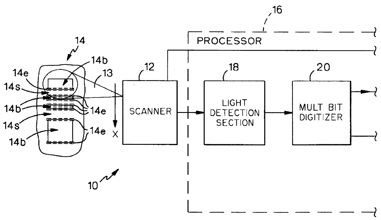
In one aspect the invention relates to a low cost adaptable multi-bit digitizer for standard and high speed scanners. In fact it will be appreciated from the following discussion that the invention may be incorporated in any system utilizing optical receivers, although the discussion that follows is limited to bar code scanners.

Standard digitizers suffer from the problem that as their sensitivity is increased in order to cope with higher density symbols, when poorly printed symbols are encountered there is a risk that defects may be interpreted as indicia to be read as a result of which the scanning time and efficiency and the processing of the signal may be increased in order to overcome the noise problem. This gives rise to a loss of "aggressiveness" for the scanner as a whole.

This problem has been addressed by applying multiple thresholds for the same scan but the hardware in such systems cannot be readily scaled for higher speed scan engines. Alternatively, where systems can be ...


PUM


Abstract

An optical scanner with plural scan beam generation. Scan angle stress is configured in the beam generation.

Description

BACKGROUND OF THE INVENTIONThis invention relates to optical scanners and signal processors used therein and more particularly to bar code scanners having multi-bit digitizers used to detect a pattern of optically reflective / non reflective white space / black bar indicia and provide multi-bit digital signal representations of such indicia.The invention further relates to a method of scanning indicia using selective sampling, particularly although not exclusively to a method of reading bar codes using a laser scanner. The invention further relates to a digitizer, for example a non-linear edge strength digitizer, to a signal processing apparatus in particular such an apparatus including a matched filter for bar code symbol reading, and to a signal processing apparatus, in particular such an apparatus including an automatic deblurring arrangement.As is known in the art, optical scanners and signal processors used therein, have a wide range of applications. One such application is in read...

Claims


Application Information

Patent Timeline
Patent Type & Authority Patents(United States)
IPC IPC(8): G06K7/14G06K7/10
CPCG06K7/10851G06K7/1478G06K7/1452G06K7/14
Inventor BRIDGELALL, RAJBARKAN, EDWARDSHELLHAMMER, STEPHENCAMPANELLI, JOSEPHKATZ, JOSEPHLI, YAJUNMCGLYNN, DANIEL R.
Owner SYMBOL TECH LLC
Why Eureka
Try Eureka