
Electrode for plasma generator the generator comprising same and process for treatment of solidifying liquid metal

a plasma generator and electrode technology, applied in plasma welding apparatus, plasma technique, manufacturing tools, etc., can solve the problems of reducing the speed at which the arc moves near the slot, forming large cavities during chilling, and dangerous presence of cooling water, so as to achieve the effect of simple and inexpensiv

Inactive Publication Date: 2001-01-02
NETANYA PLASMATEK LTD
View PDF11 Cites 10 Cited by
  • Summary
  • Abstract
  • Description
  • Claims
  • Application Information

AI Technical Summary

Benefits of technology

It is one object of the present invention to provide a simple and inexpensive electrode for a plasma arc generator, adapted to generate a continuously circulating, self-stabilized plasma arc with no need for any water cooling or injection of a protecting gas, and which at least up to an output of about 50 kW may operate for considerable spans of time.
It is a still further object of the present invention to provide an improved process for heat treatment of solidifying liquid metal in molds with a circulating plasma arc.

Problems solved by technology

It is an intrinsic disadvantage of the conventional plasma generators of both the non-transferable and transferable types, that for proper functioning the injection of a protecting gas or water cooling are required.
Injection of a pressurized inert gas into the torch is associated with the formation of an elongated plasma jet ejected at high velocity from the plasma delivery nozzle which in case of treatment of a solidifying cast metal causes the exertion of localized pressure on the surface of the still solidifying metal, leading to the formation of large cavities during chilling.
The presence of cooling water is dangerous because any leaking water that reaches the hot liquid metal may cause an explosion.
However, when crossing any of the slots the arc arrives exactly at the zone of the adjacent electric contact, where direction of its further movement is indefinite, and consequently the speed at which the arc moves near the slots is reduced and the discharge is occasionally even interrupted, which is an obvious disadvantage.
(a) manufacture of the spiral electrode from graphite or tungsten or some other material conventionally used for making electrodes for plasma arc generators, is difficult and expensive;
(b) due to the exponential increase of Y as a function of X, the plasma current fluctuates and consequently, in practice, a plasma arc generator according to SU 847533 is capable of operating reliably without auxiliary means only up to a spiral diameter of not more than 6 cm., while at larger diameters interruptions of the plasma arc might occur. To preempt such interruptions, the plasma arc discharge must be re-ignited at every cycle by means of a high-voltage oscillator;
(c) since the plasma is accelerated non-uniformly along the spiral proximal electrode rim, the electrode is heated in a non-uniform fashion which requires an efficient and reliable water cooling system with appropriate instrumentation for effective water temperature and pressure control. All this renders the plasma generator expensive and renders impossible its applications for missions where use of cooling water is undesirable because of the dangerous consequences of any leakage.

Method used


Image

  • Electrode for plasma generator the generator comprising same and process for treatment of solidifying liquid metal
  • Electrode for plasma generator the generator comprising same and process for treatment of solidifying liquid metal
  • Electrode for plasma generator the generator comprising same and process for treatment of solidifying liquid metal

Examples


Embodiment Construction

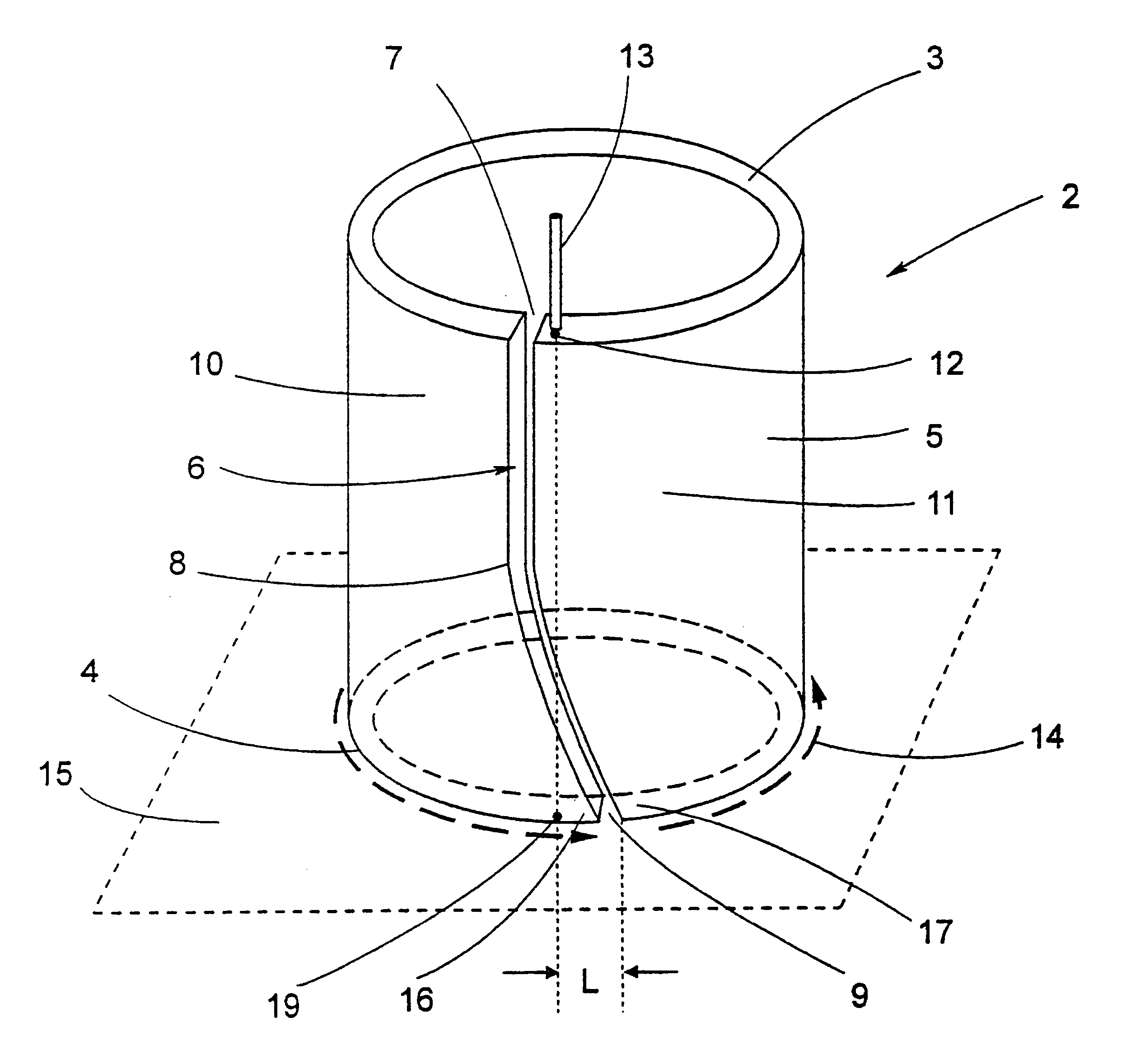
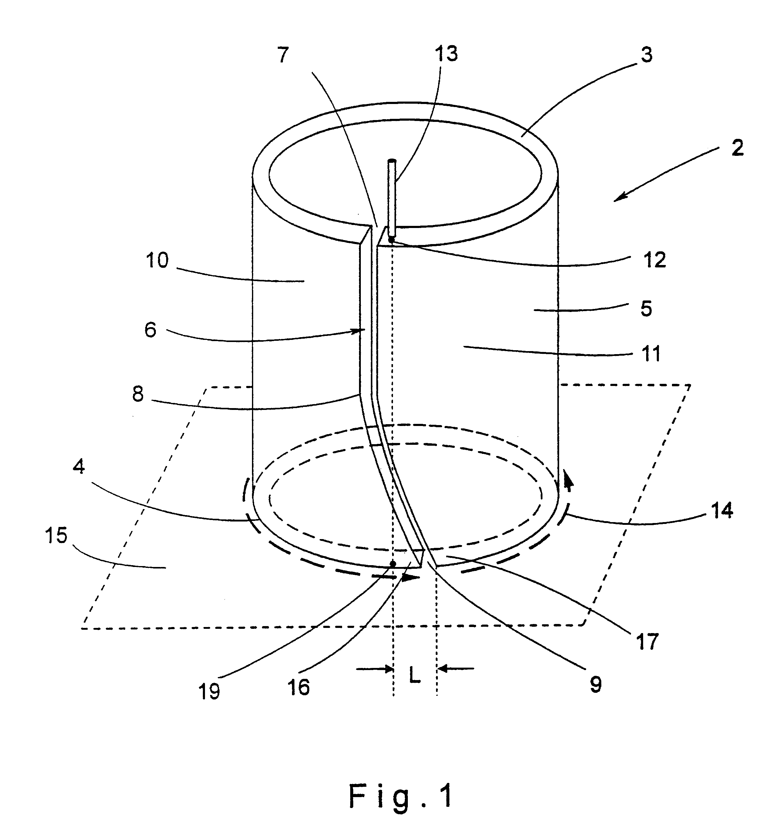
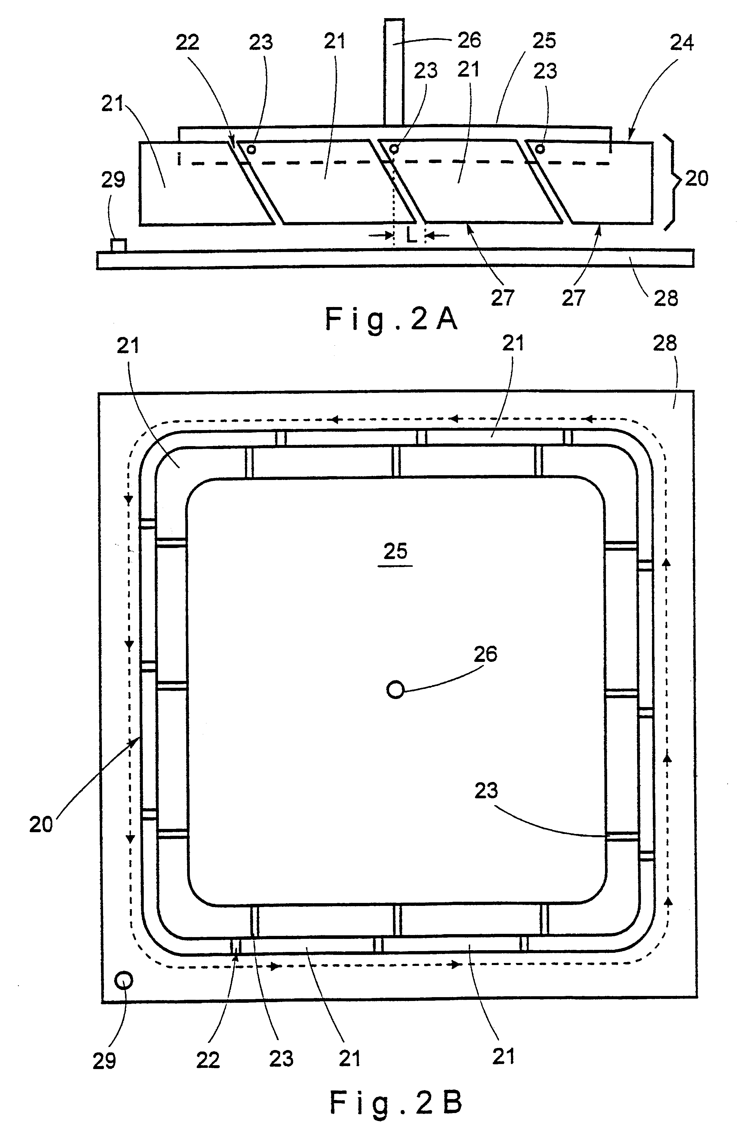
FIG. 1 illustrates a perspective view of one embodiment of a plasma arc generating electrode according to the invention. As shown, electrode 2 comprises a tubular cylindrical body having a longitudinal axis, a first rim 3, a second, working rim 4 serving for the electric arc discharge and being a constituent of a two-rail structure which in operation defines a closed path for the movement of the electric arc in consequence of a Lorentz force generated in the device. Side wall 5 of the cylindrical electrode body is sliced by a single throughgoing gap 6 generally extending in the axial direction and having a first rim region gap stretch 7, a main gap stretch 8 and a second rim region gap stretch 9. As shown, the main gap stretch 8 comprises two parts forming between them an obtuse angle. Gap 6 divides between two sectors 10 and 11 of wall 5. Electrode 2 has on the first rim 3 a gap-associated connector site 12 fitted with a connector 13 serving for connection to a pole of a d.c. power...


PUM

PropertyMeasurementUnit
Fractionaaaaaaaaaa
Forceaaaaaaaaaa
Angleaaaaaaaaaa

Abstract

A main electrode (2, 20, 30, 44, 127) for plasma arc generator, a generator (50, 70, 80, 126) comprising same and a process for treatment of solidifying liquid metal by the mentioned generator, wherein the main electrode in association with a counter electrode (15, 28, 42, 54, 73, 86, 122) provides a two-rail structure capable of generating a plasma arc discharge displaceable along a closed path uninterruptedly. The uninterrupted movement of the arc discharge is achieved by a specific design of the main electrode. The electrode comprises an essentially tubular body having a first rim (3, 24, 33, 89) usually connected to a d.c. power source via at least one connector site (12), and a second, working rim (4, 27, 34, 46, 63, 78, 90) serving for the electric arc discharge. The tubular body is divided by at least one slot (gap) (6, 22, 32, 49, 52, 88) associated with one connector site and extending between the first and second rims so that it forms at the second rim region a second rim gap. Two sides of the second rim gap are an arc transmitting (16, 36) and an arc receiving (17, 35) zones, respectively. Mutual positions of these two zones and the associated connector site are such, that when the arc column is created and displaces along the second rim, it will always be transmitted from the transmitting zone to the receiving zone at a location positioned downstream from the projection of the associated connector site to the second rim (in respect of the direction of the plasma arc movement). Owing to this arrangement the arc column will cross the second rim gaps uninterruptedly.

Description

The present invention relates to plasma arc generators of both the transferable and non-transferable types, and more specifically to plasma apparatus of the kind generating a plasma arc that circulates in a closed path. The invention further relates to an electrode for use in plasma generators of the kind specified.Plasma arc generators are used for the heat treatment of various objects in numerous technological processes, for example in metallurgical processes for so-called plasma remelting, plasma casting, plasma cleaning, etc. By one of its aspects, the invention relates to a process for heating with a circulating plasma arc a liquid metal chilling and crystallizing within a mold, with the object of eliminating typical casting defects, such as the formation of blowholes and porosity, segregation, formation of contraction cavities, inhomogeneity of chemical composition and crystal structure across the ingot, etc.Plasma generators including plasma arc torches are known in the art, ...

Claims


Application Information

Patent Timeline
IPC IPC(8): H05H1/48H05H1/24B22D27/02H05H1/34
CPCH05H1/48B22D11/10
Inventor DVOSKIN, PAVELZLOCHEVSKY, VALERYROSEN, RAN
Owner NETANYA PLASMATEK LTD
Learn More