Apparatus and method including a handpiece for synchronizing the pulsing of a light source

a technology of light source and handpiece, which is applied in the field of apparatus and methods including handpieces for synchronizing the pulsing of light source, can solve the problems of undesirable skin over-exposure and difficulty in manually controlling the positioning and activation of laser light source, and achieve the effect of reducing the risk of over-exposur

Inactive Publication Date: 2001-01-09
TALPALRIU GERARD +4
View PDF5 Cites 61 Cited by
  • Summary
  • Abstract
  • Description
  • Claims
  • Application Information

AI Technical Summary

Benefits of technology

It is therefore an object of the present invention to provide a system for enabling an operator to apply radiation to a surface of tissue in a substantially uniform way and to reduce the risk of over-exposure of the treated tissue by reducing the possibility of repeatedly irradiating the same area of tissue during the same treatment session.

Problems solved by technology

Since the depilating beam does not leave any visible mark on the skin, the operator has to memorize or keep track of the already treated area otherwise he might inadvertently irradiate the same skin area repeatedly, thus causing undesirable over-exposure of the skin.
Additionally, it can be difficult to manually control the positioning and activation of the laser light source so as to achieve a uniform irradiation of the skin area without leaving non-irradiated areas or causing undesirable over-exposure of skin areas.

Method used


Image

  • Apparatus and method including a handpiece for synchronizing the pulsing of a light source
  • Apparatus and method including a handpiece for synchronizing the pulsing of a light source
  • Apparatus and method including a handpiece for synchronizing the pulsing of a light source

Examples


Embodiment Construction

It will be appreciated that, while the system disclosed hereinbelow is described as using a pulsed or a continuous wave laser as the source of electromagnetic radiation, the system can be used with any other suitable radiation sources such as any source of continuous or pulsed light or other sources of non-coherent electromagnetic radiation or any other source of radiation useful for therapeutic or cosmetic purposes. Thus, the term light refers throughout the specification and claims not only to visible light but to any of the radiation types referred to hereinabove.

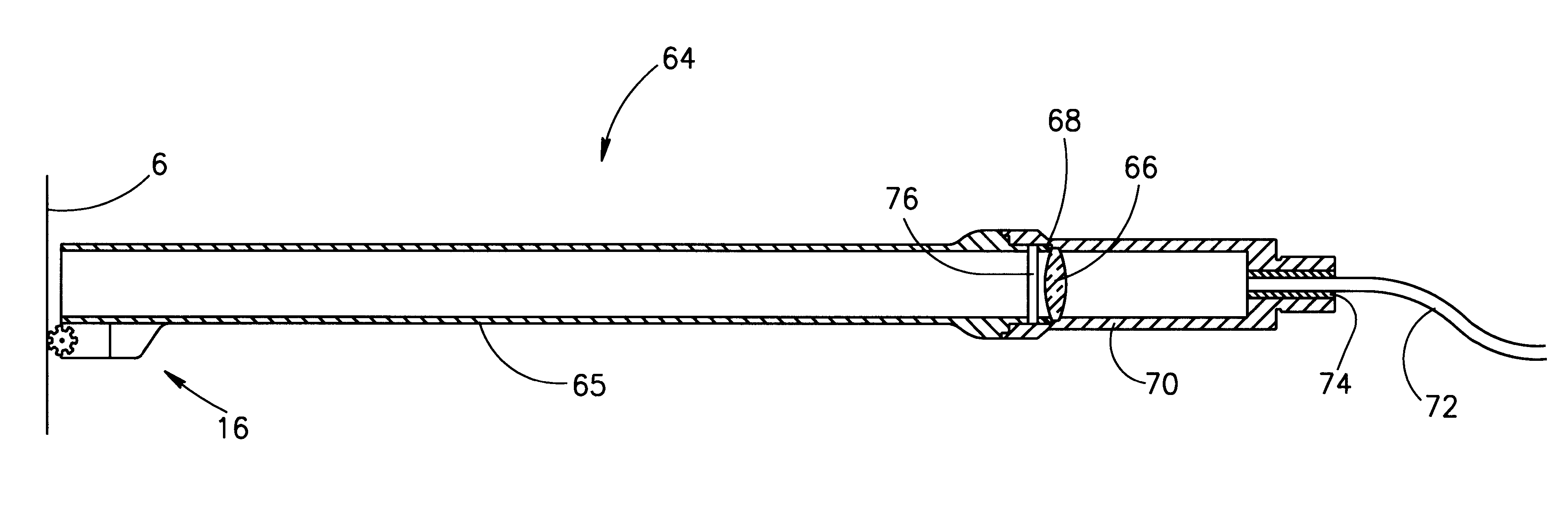
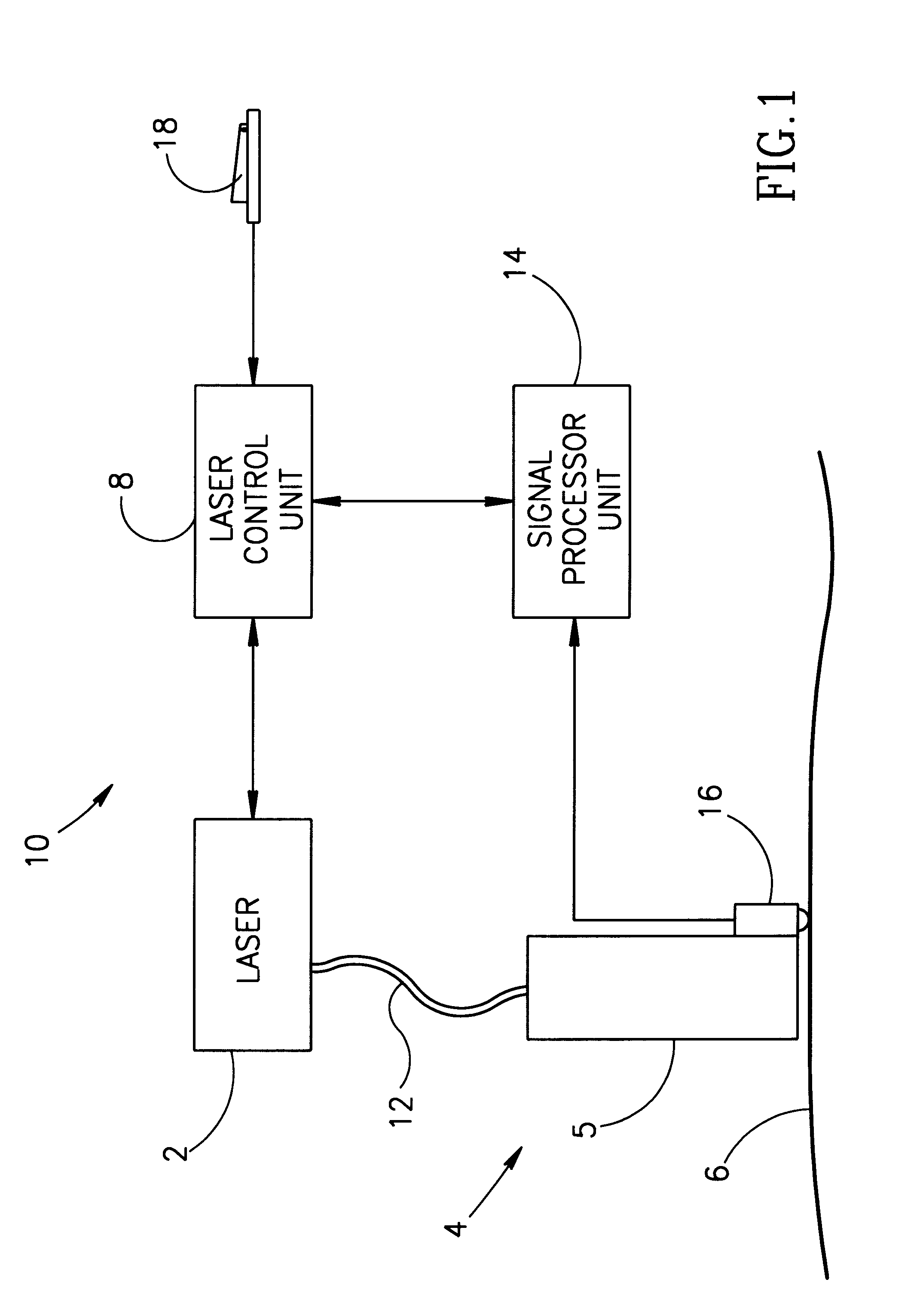
Reference is now made to FIG. 1 which is a schematic block diagram illustrating a system 10 for controlling the exposure of a surface of a tissue to laser radiation in accordance with a preferred embodiment of the present invention. System 10 includes a laser 2 connected to a handpiece 4 by a suitable beam delivery system 12. The beam delivery system 12 can be any suitable delivery system such as an optical fiber, an opt...


PUM


Abstract

The present application discloses an apparatus and a method for synchronizing the activation of a light source with the position of a hand piece on a surface and for providing a substantially homogenous exposure of a surface to light irradiation. The apparatus includes a light source, a handpiece for delivering light pulses to the irradiated surface, and a beam delivery system for delivering light from the light source to the handpiece. The handpiece, which is moved along the surface by an operator, includes a sensor for sensing the distance traversed by the handpiece on the surface. The sensor sends signals to a signal processing unit which calculates the distance traversed by the handpiece on the surface and controls the activation of the light source either by automatically activating the light source or by providing the operator with a signal indicating that the light source should be pulsed. The handpiece can also include a device for cooling the irradiated surface and for marking the irradiated part of the surface with a visible marker. The handpiece may be constructed to be movable along a surface in a predetermined orientation relative to the handpiece. Alternatively, the handpiece may be freely movable along the surface in any desired orientation. The light source can be a pulsed laser, a continuous wave laser or a non-coherent light source.

Description

The present invention relates to apparatus for enabling controlled activation of a device for treatment of tissue by an operator. The invention is particularly useful for controlling the activation of lasers used for skin treatment, and is therefore described below with respect to this application.A variety of medical and cosmetic treatment methods involve exposure of a defined area of tissue to electromagnetic radiation such as light of various wavelength. The light source can be a non-coherent light source such as a suitable lamp or a coherent light source such as a laser.The application of lasers for therapeutic or cosmetic skin treatment is known in the art. For example laser radiation is used for facial rejuvenation as disclosed in U.S. Patent Application, titled Laser Facial Rejuvenation, Ser. No. 08 / 382,918 to Slatkine and Mead filed on Feb. 2, 1995. Another example is the use of laser irradiation for hair removal as disclosed in U.S. Provisional Application Ser. No. 60 / 008,8...

Claims


Application Information

Patent Timeline
Patent Type & Authority Patents(United States)
IPC IPC(8): A61B18/20A61B19/00A61B17/00
CPCA61B18/203A61B2017/00057A61B2018/00452A61B2018/0047A61B2019/461A61B2019/545
Inventor TALPALRIU, GERARDROZENBERG, YTZHAKHAY, NISSIMZOBEL, IZHAKABRAHAM, MARTIN
Owner TALPALRIU GERARD
Why Eureka
Try Eureka