Low inductance electrical machine for flywheel energy storage

a low-inductance, electrical machine technology, applied in the direction of synchronous motors, magnetic circuit rotating parts, magnetic circuit shapes/forms/construction, etc., can solve the problems of high output inductance, substantial design challenge, and difficulty in the operation of high-frequency alternators or generators

Inactive Publication Date: 2001-01-16
RAVEN TECH
View PDF15 Cites 87 Cited by
  • Summary
  • Abstract
  • Description
  • Claims
  • Application Information

AI Technical Summary

Problems solved by technology

While this has not been much of an issue for 60 Hz synchronous generators, it becomes a substantial design challenge for high frequency alternators.
A disadvantage of these physically small claw pole units is that the close proximity of multiple poles and multiple magnetic pathways allows for unnecessary storage of substantial amounts of magnetic energy, resulting in high output inductance.
High output inductance causes several difficulties in the operation of high frequency alternators or generators.
Since core losses due to eddy current generation are proportionate to both the frequency squared and the magnetic intensity level squared it will be understood that the need for extra excitation to overcome the inductive impedance of the output will lead to high core losses at high frequency operation.
Also, it is common for the output inductance of one phase to be linked by mutual inductance to the output of other phases so that the sudden change in current (switching) in one phase produces unwanted voltage transients in the other phases.
As noted for the typical high frequency alternators, such as the claw pole type, the close proximity of multiple poles and magnetic paths gives rise to the unnecessary storage of large amounts of magnetic energy.
In physically compact machines where many poles and pathways are arranged in close proximity the leakage flux can become a high percentage of flux, making the machine inefficient.
The rotors in these designs are relatively complex, present difficulties in establishment of air gap clearances, and do not a

Method used


Image

  • Low inductance electrical machine for flywheel energy storage
  • Low inductance electrical machine for flywheel energy storage
  • Low inductance electrical machine for flywheel energy storage

Examples


Embodiment Construction

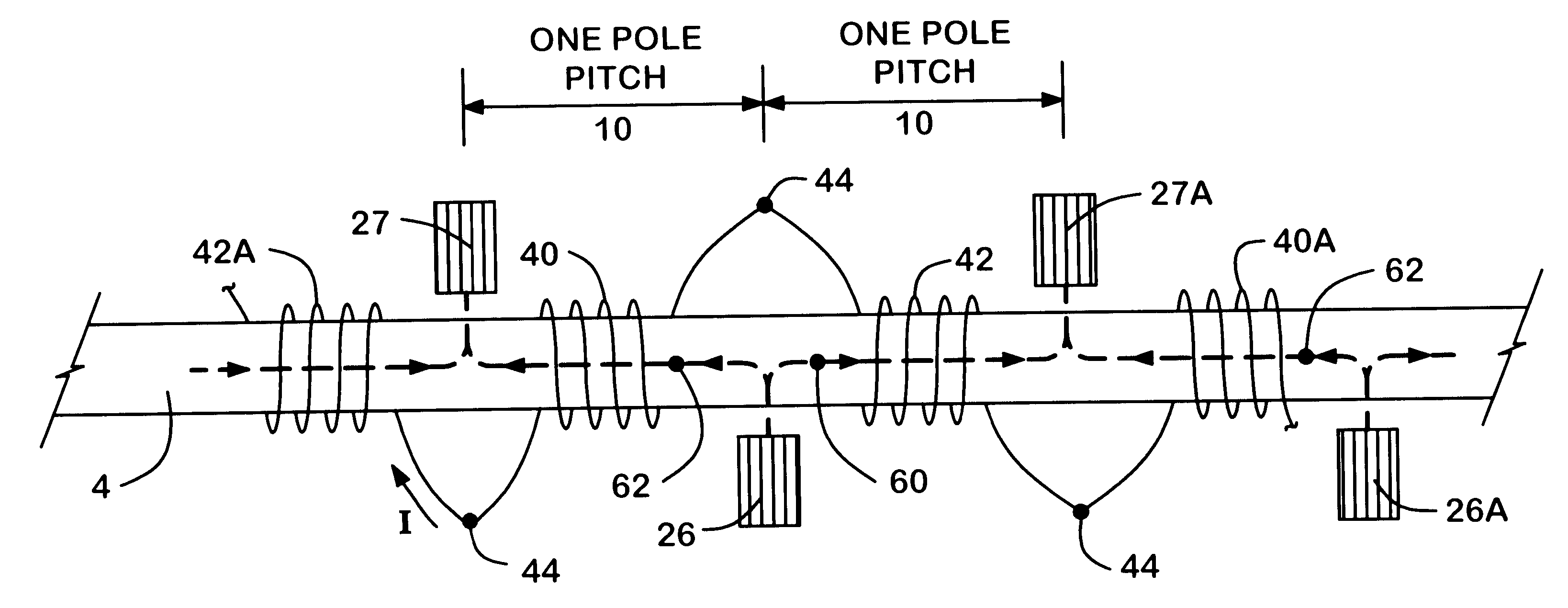
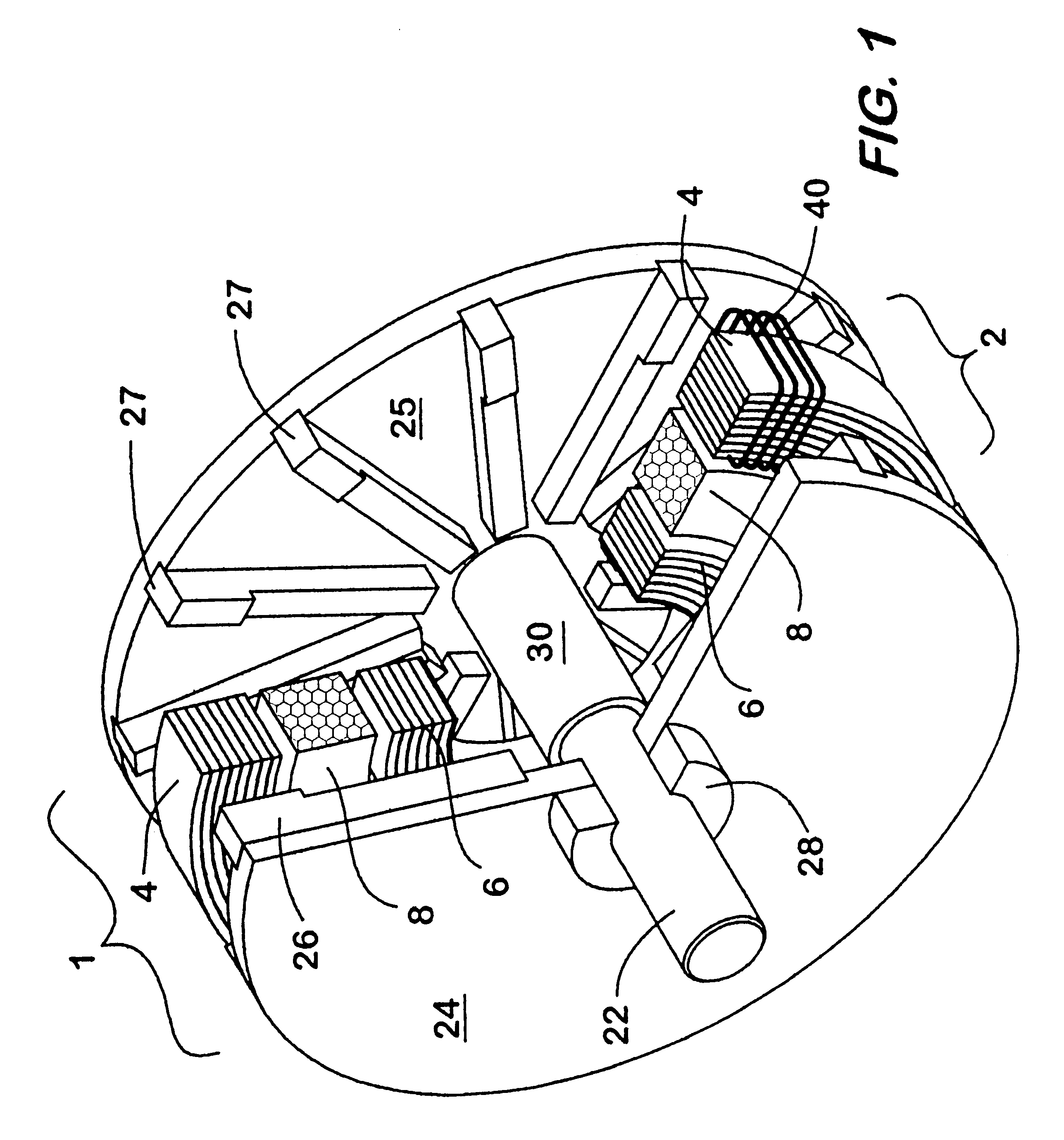
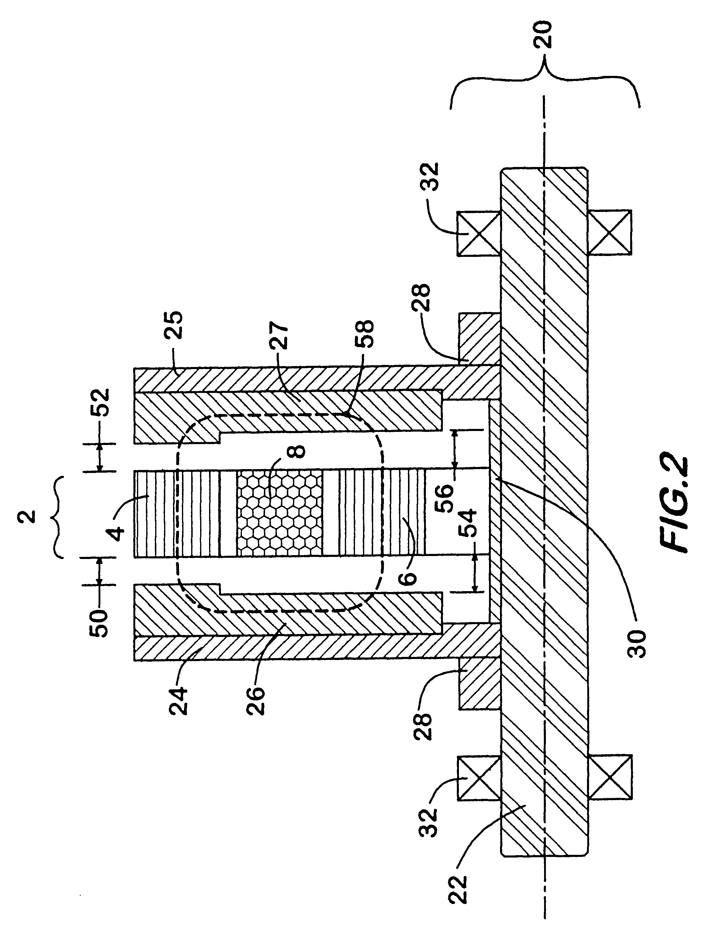
In a first embodiment, the low inductance electrical machine of the present invention is configured as a high frequency alternator. Referring to FIG. 1, the low output inductance electrical machine 1 of the present invention includes a stator assembly 2 including an outer annular ring 4 and an inner annular ring 6, both made substantially of laminated electrical or magnetic steel or other suitable magnetic material with low core loss characteristics in order to minimize eddy current losses and hysteresis losses in the stator, and in this embodiment manufactured by making a spiral winding of appropriate material. An annular field coil winding 8 of insulated copper wire or other suitable conductor is wound toroidially and located coaxially between the two stator rings 4 and 6, and provides means by which the stator and rotor may be excited by an external current source. Armature windings 40 are wound poloidially around sections of the outer stator ring 4 in a specific manner which wil...


PUM


Abstract

A low inductance electrical machine which may be used as an alternator or motor with low armature inductance is disclosed. Arrangements of complementary armature windings are presented in which the fluxes induced by currents in the armature windings effectively cancel leading to low magnetic energy storage within the machine. This leads to low net flux levels, low core losses, low inductance and reduced tendency toward magnetic saturation. Separately excited field arrangements are disclosed that allow rotor motion to effect brushless alternator or brushless motor operation. An exemplary geometry includes a stator including two toroidal rings and a concentric field coil together with a rotor structure separated from the stator by four air gaps. An alternate embodiment allows for counter-rotation of two rotor elements for use as a flywheel energy storage system in which the external gyroscopic effects cancel.

Description

1. Field of InventionThis invention relates generally to the design of electrical machines, and more particularly to the design of alternators, generators and motors having low inductance in the armature circuits with particular emphasis on use in flywheel energy storage systems2. Description of the Prior ArtAs is well understood by those skilled in the art, electrical machines have an internal impedance that interacts with other system impedance to determine the performance of the combined system. In a motor, the inductance is that portion of the internal impedance related to magnetic energy storage within the electrical machine as it is energized to deliver mechanical work. The electrical system driving the motor must deliver the energy to be stored in the inductor in addition to the energy for the mechanical work to be performed. This necessitates increases in the capacity of generators, wiring and transformers needed to supply the motor.In alternators and generators the internal...

Claims


Application Information

Patent Timeline
IPC IPC(8): H02K7/00H02K7/02H02K21/44H02K21/12H02K19/02H02K16/00H02K19/10H02K19/24H02K16/02H02K21/24H02K19/16H02K21/00
CPCH02K7/025H02K16/02H02K19/103H02K19/24H02K21/24H02K21/44Y02E60/16H02K16/00
Inventor TUPPER, CHRISTOPHER N.WOOD, DUNCAN G.
Owner RAVEN TECH
Why Eureka
Try Eureka