Positioning apparatus

a technology of positioning apparatus and positioning rod, which is applied in the direction of hoisting equipment, gearing, manufacturing tools, etc., can solve the problems of affecting the resolution of slide devices, fluctuating speed, and affecting the stability of slide devices

Inactive Publication Date: 2001-01-30
NTN CORP
View PDF16 Cites 5 Cited by
  • Summary
  • Abstract
  • Description
  • Claims
  • Application Information

AI Technical Summary

Benefits of technology

A further object of the present invention is to provide an improved positioning apparatus of the type referred to above, wherein the factor, such as a yawing, which leads to reduction in accuracy, is minimized; which is less susceptible to deviation in speed to accomplish a stabilized feed and which is robust against an external disturbance enough to increase the resolution.
According to this structure, since the support by the external pressure and the frictional reciprocating drive mechanism are combined, a demerit of the support by the external pressure can be compensated for. Also, since the frictional reciprocating drive mechanism is made up of component parts of a simplified shape such as a main shaft made of a round shaft, and rollers held in contact with the main shaft while inclined relative thereto and since such simplified component parts can easily be machined with high precision, a stabilized feed can be accomplished with no fluctuation occurring in speed. For these reasons, the positioning resolution can be increased to accomplish a high density write-in.

Problems solved by technology

It has, however, been found that the slide device utilizing the linear motor of the voice-coil type is of a completely non-contact design, the slide device tends to be adversely affected by an external disturbance.
For this reason, improvement in resolution has hitherto been limited.
On the other hand, the slide device utilizing the ball screw for driving the slide body, the presence of an error in shape of a helical groove and / or diameter of balls tends to result in fluctuation in speed so as to bring about a shaking motion of the slide body in a direction axially of a shaft.
However, even this frictional reciprocating drive mechanism is unable to accomplish a highly accurate drive of the main shaft, failing to achieve a precise positioning of the slide body, because of the presence of an influence brought about by a fluctuated rotation of the motor and / or a phase deviation occurring in a transmission system for transmitting the rotation of the motor to the main shaft.
In addition, the conventional externally pressurized linear bearing assembly has been found difficult to secure a sufficient rigidity of the bearing assembly and the lack of a sufficient rigidity tends to adversely affect the accuracy of positioning.
The apparatus in which the pneumatic slide device having the linear motor of the voice-coil type discussed above is utilized, or the apparatus in which the ball screw is utilized to drive the slide body, inherently involve a factor such as, for example, a yawing that tends to reduce the accuracy and, therefore, a highly accurate positioning is difficult to achieve.
Yet, since the accuracy of positioning is limited because of fluctuation in speed of movement of the slide body, a high density write-in is difficult to achieve where the pneumatic slide device is utilized.

Method used


Image

  • Positioning apparatus
  • Positioning apparatus
  • Positioning apparatus

Examples


Embodiment Construction

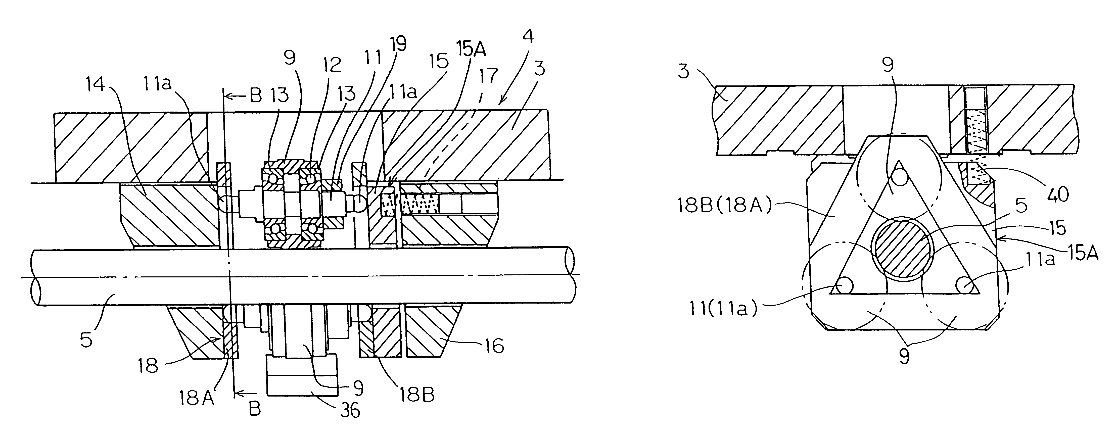
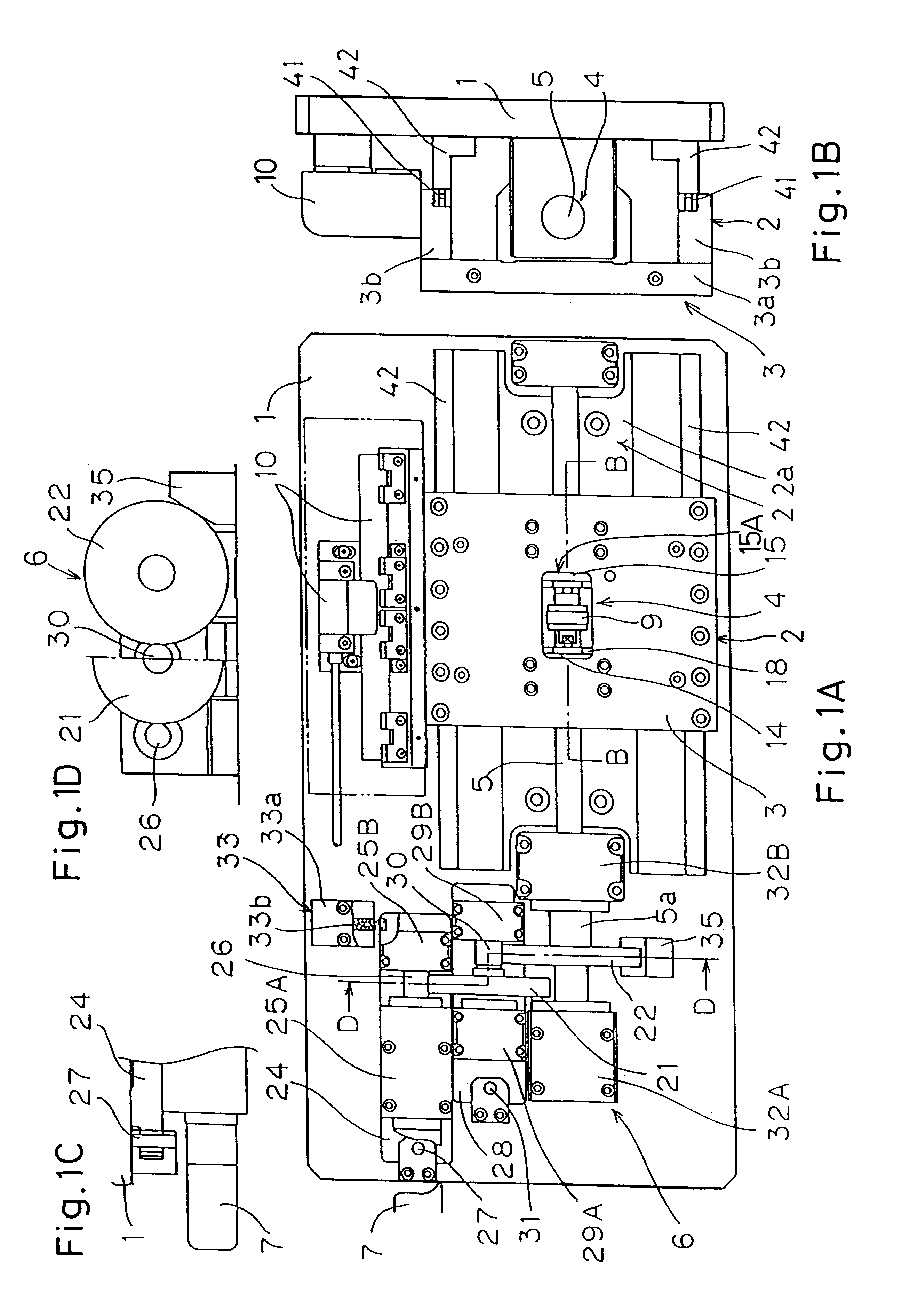
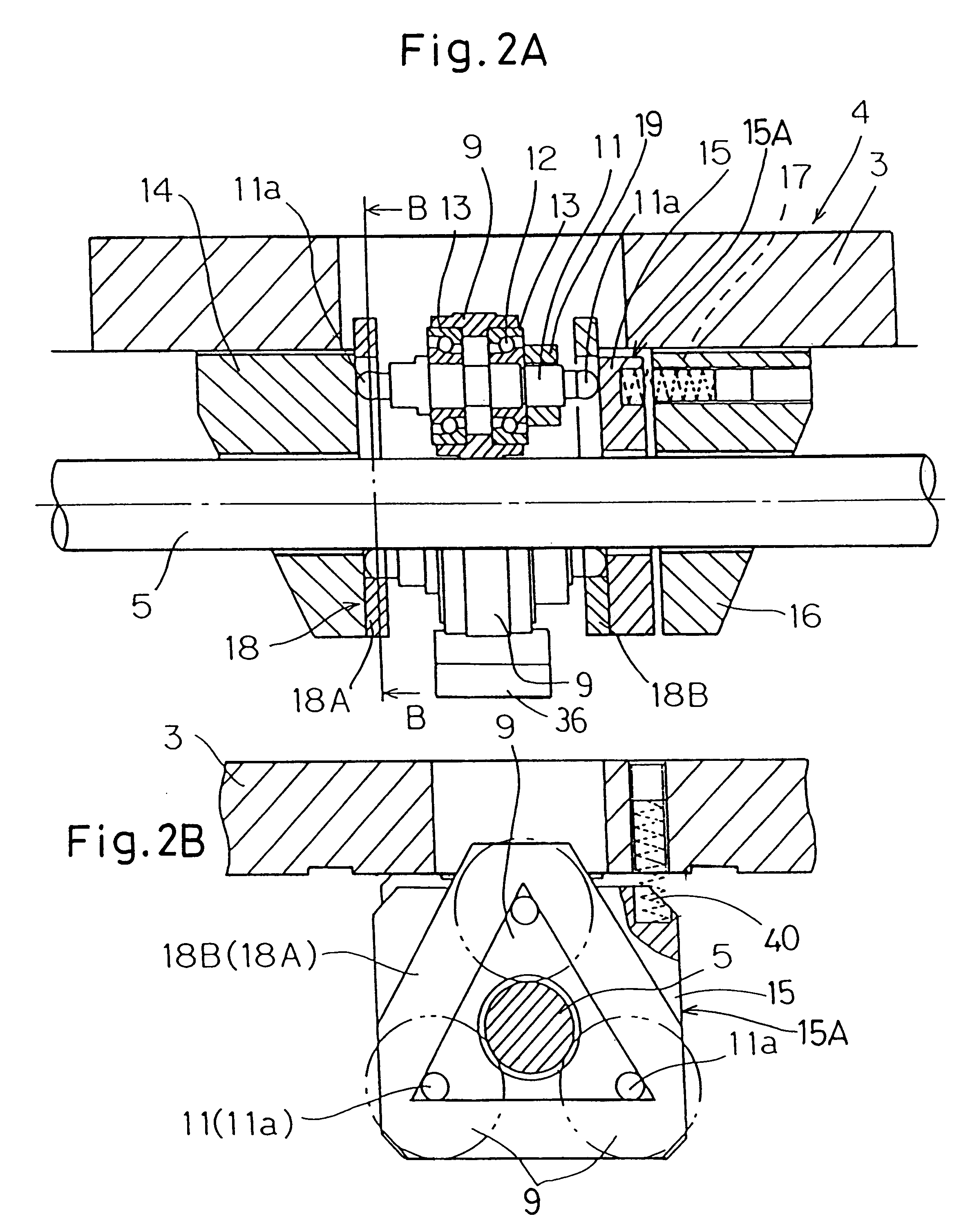
Reference will now be made to the accompanying drawings for the detailed discussion of the positioning apparatus according to the present invention. As best shown in FIG. 1A, the positioning apparatus includes a slide body 3 serving as a support table and mounted on a machine bench 1 for movement between advanced and retracted positions by means of an externally pressurized linear bearing assembly 2. The positioning apparatus also includes a frictional reciprocating drive mechanism 4 having a main shaft 5 positioned intermediate of the width of the externally pressurized linear bearing assembly 2. The slide body 3 is of a generally saddle-like configuration including, as best shown in FIG. 1B, a generally rectangular top plate 3a and a pair of side plates 3b extending downwardly from respective opposite ends of the top plate 3a so as to lie perpendicular to the top plate 3a. This slide body 3 straddles a guide rail 20 that is accommodated within a space delimited by the top and side...


PUM


Abstract

A positioning apparatus includes a machine bench 1, an external pressure linear bearing assembly 2 and a slide body 3 mounted on the machine bench 1 through the bearing assembly 2 for reciprocating movement relative to the machine bench. The positioning apparatus has a frictional reciprocating drive mechanism 4 for reciprocatingly driving the slide body 3 which is provided and includes a main shaft 5 adapted to be rotated, and a plurality of rollers 9 disposed around the main shaft 5 and inclined at a predetermined angle relative to the main shaft 5. Each roller 9 is pressed relative to the main shaft 5 by a pressing member 15. The slide 3 and a rail 20 are made of ceramics. Magnets 41 are provided on the slide body 3 for developing forces of magnetic attraction between magnetizable members 42, provided on the machine bench 1, and the slide body 3.

Description

1. Field of the InventionThe present invention relates to a positioning apparatus for positioning a slide body used in a precision machine such as, for example, an optical disc mastering machine or a semiconductor testing machine, and a frictional reciprocating drive mechanism used for reciprocatingly driving the slide body.2. Description of the Prior ArtIn a machine such as, for example, an optical disc mastering machine or a semiconductor testing machine, which requires a high precision, a pneumatic slide device in which a slide body is installed for reciprocating movement through an externally pressurized linear bearing assembly has hitherto been employed largely. For driving the slide body, a linear motor of a voice-coil type is generally employed and a closed loop control system is employed in which an interference laser measuring instrument or a linear scale is employed for a position detector. Also, in an apparatus such as, for example, the semiconductor testing machine, in w...

Claims


Application Information

Patent Timeline
Patent Type & Authority Patents(United States)
IPC IPC(8): B23Q1/58B23Q5/38B23Q5/22B23Q1/25F16H19/00F16H19/02
CPCB23Q1/58F16H19/025B23Q5/385Y10T74/18568
Inventor MIYAKE, TORUOKADA, MANABU
Owner NTN CORP
Why Eureka
Try Eureka