Compact fuel gas reformer assemblage

a fuel gas reformer and compact technology, applied in the direction of combustible gas production, lighting and heating apparatus, combustion types, etc., can solve the problems of unsatisfactory large and heavy reformer assembly

Inactive Publication Date: 2001-03-20
INT FUEL CELLS
View PDF6 Cites 85 Cited by
  • Summary
  • Abstract
  • Description
  • Claims
  • Application Information

AI Technical Summary

Benefits of technology

It is a further object of this invention to provide a reformer assembly of the character described which operates at lower temperatures than presently available reformer assemblies due to enhanced heat transfer properties of the assembly.
It is yet another object of this invention to provide a reformer assembly of the character described which has high surface area catalytic surfaces that are exposed to the process fuel gases flowing through the assembly.

Problems solved by technology

This need for large catalyst bed and heat transfer surface area, when met by using catalyst-coated (hereinafter "catalyzed") pellets in tubular reformers, results in undesirably large and heavy reformer assemblies.

Method used


Image

  • Compact fuel gas reformer assemblage
  • Compact fuel gas reformer assemblage
  • Compact fuel gas reformer assemblage

Examples


Embodiment Construction

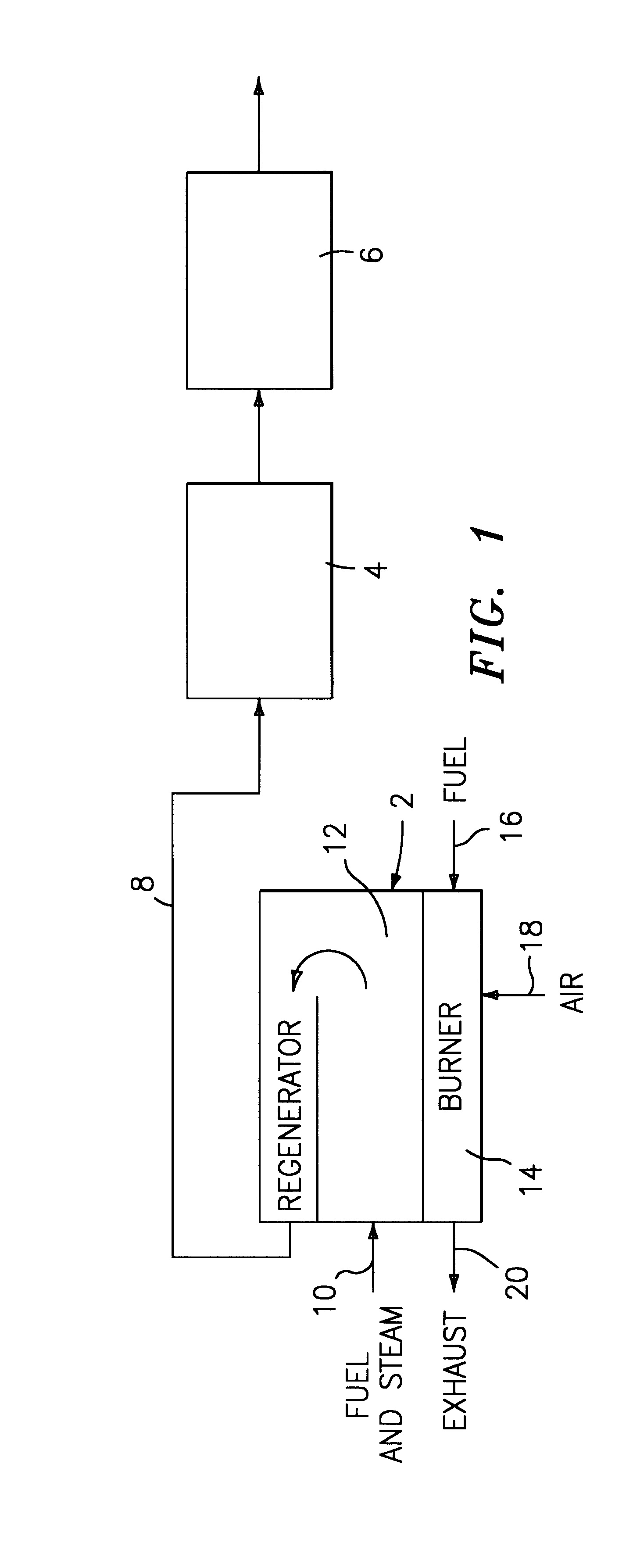
Referring now to the drawings, there is shown in FIG. 1 a schematic view of a fuel processing assembly which forms a portion of a typical fuel cell power plant. The fuel processing assembly includes a fuel steam reformer regenerator station 2; a shift converter station 4; and a selective oxidizer station 6 which may be required for certain fuel cells that are intolerant to high levels of carbon monoxide. The reformer-regenerator 2 is connected to a shift converter 4 by means of a line 8. The reformer-regenerator station 2 includes a fuel and steam inlet line 10 which feeds the fuel and steam mixture into the catalyzed reformer zone 12. A mixture of partially spent fuel from the fuel cell stack and air is fed into a burner component 14 via lines 16 and 18. The aforesaid mixture is combusted therein to heat the fuel and steam mixture to reacting temperatures. The burner 14 is exhausted from the reformer-regenerator 2 via line 20.

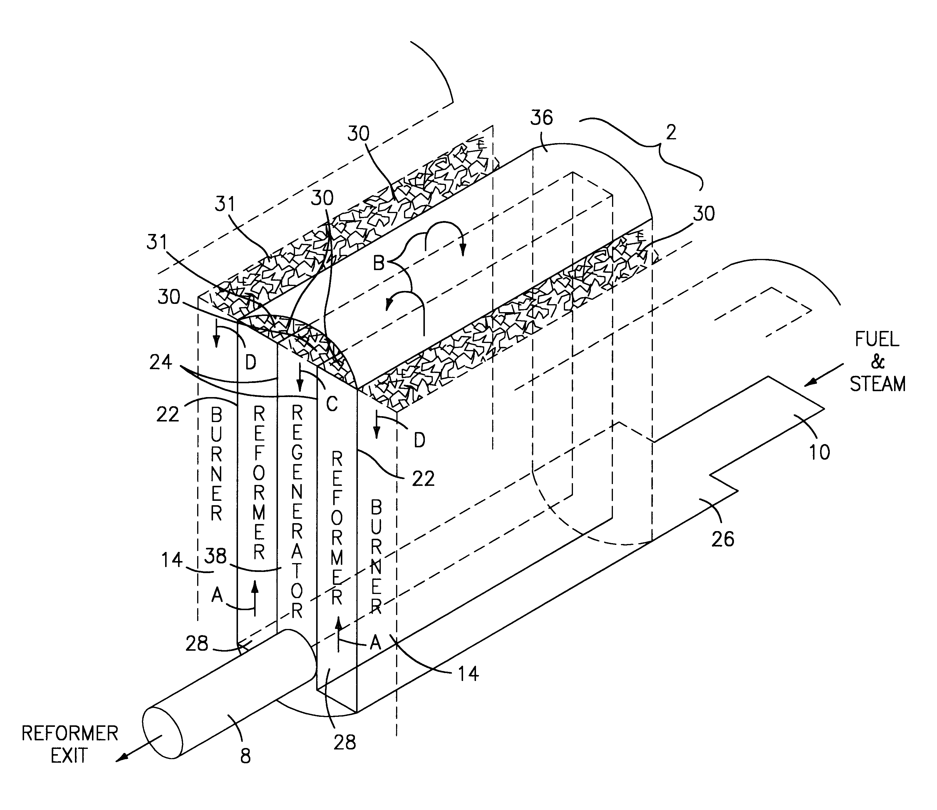
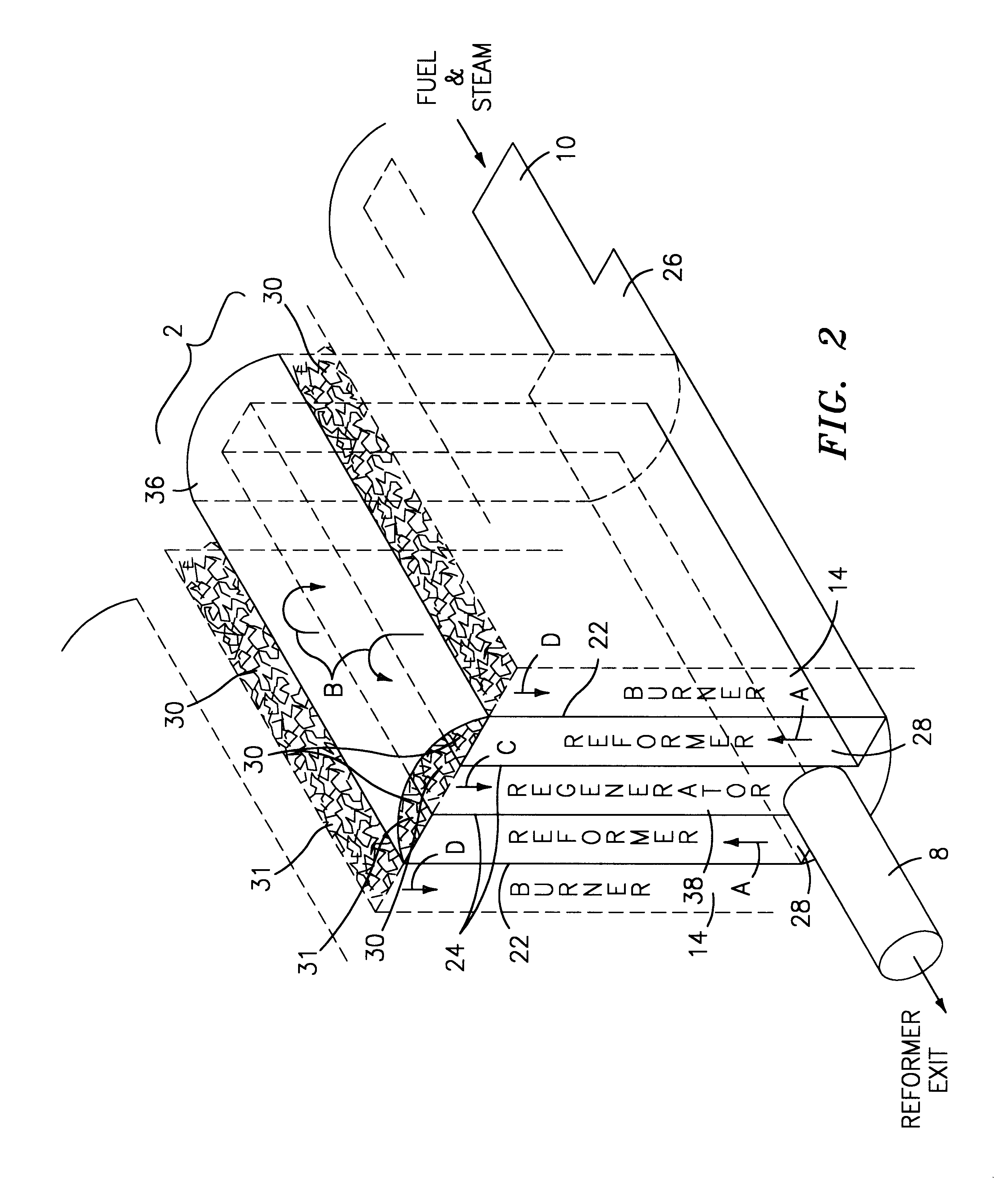
FIG. 2 is a schematic representation of an embodiment of...


PUM

PropertyMeasurementUnit
temperatureaaaaaaaaaa
volumeaaaaaaaaaa
heat transferaaaaaaaaaa

Abstract

A fuel gas reformer assemblage for use in a fuel cell power plant is formed from a composite plate assembly which includes spaced-apart divider plates with interposed monolithic open cell sponge-like members which form gas passages. The monolithic members have a lattice of internal open cells which are both laterally and longitudinally interconnected so as to provide for a diffuse gas flow. The entire surface area of the monolithic components is wash coated with a porous alumina layer, and selected areas of the wash coat are also catalyzed. The reformer assemblage is constructed from a series of repeating sub-assemblies, each of which includes a core of separate regenerator / heat exchanger gas passages. The core in each sub-assembly is sandwiched between a pair of reformer gas passage skins, which complete the subassembly. Adjacent reformer gas / regenerator / reformer gas passage sub-assemblies in the composite plate assembly are separated from each other by burner gas passages. The regenerator / heat exchanger gas passages and the reformer gas passages in each sub-assembly are connected by gas flow return manifolds which form a part of each sub-assembly. The fuel gases flow in one end of the assemblage, through the reformer gas passages, and then reverse their direction of flow in the return manifolds so as to exit the reformer assemblage through the regenerator gas flow passages. The burner gases flow in one end of the reformer assemblage and out the other end.

Description

DESCRIPTION1. Technical FieldThis invention relates to a fuel gas steam reformer assemblage which is formed from a plurality of repeating sub-assemblies. More particularly, this invention relates to a fuel gas steam reformer assemblage which is compact and lighter in weight than conventional steam reformer assemblages used in fuel cell power plants.2. Background ArtFuel cell power plants include fuel gas steam reformers which are operable to catalytically convert a fuel gas, such as natural gas, into hydrogen and carbon dioxide. The conversion involves passing a mixture of the fuel gas and steam through a catalytic bed which is heated to a reforming temperature of about 1,250.degree. F. to about 1,600.degree. F. Catalysts typically used are nickel catalysts which are deposited on alumina pellets. A typical reformer will consist of a plurality of reaction tubes which are contained in a housing that is insulated for heat retention. The reaction tubes are heated by burning excess fuel ...

Claims


Application Information

Patent Timeline
Patent Type & Authority Patents(United States)
IPC IPC(8): B01J19/24C01B3/38C01B3/00C01B3/48C01B3/58H01M8/06B01J8/02F23D14/18
CPCB01J19/2485B01J19/249C01B3/384C01B3/48C01B3/583B01J2219/00117B01J2219/00157B01J2219/2453B01J2219/2458B01J2219/2462B01J2219/2479B01J2219/2485C01B2203/0233C01B2203/0283C01B2203/044C01B2203/047C01B2203/066C01B2203/0811C01B2203/0844C01B2203/0866C01B2203/0883C01B2203/1023C01B2203/1052C01B2203/1064C01B2203/1082H01M8/0631Y02E60/50
Inventor LESIEUR, ROGER R.CORRIGAN, THOMAS J.
Owner INT FUEL CELLS
Why Eureka
Try Eureka