Blood pulse measuring device, pulsation measuring device, and pressure measuring device

a technology of pulsation measuring device and pressure measuring device, which is applied in the field of blood pulse measuring device, pulsation measuring device, pressure measuring device, etc., can solve the problems of difficult to accurately position the pressure measuring device mounted on the cuff above the blood vessel, difficult to adjust the initial pressure of the blood vessel using such cuffs, and individual differences among patients, so as to reduce the strain energy accumulated in the beam, the effect of reducing the strain energy of the piezo

Inactive Publication Date: 2001-04-03
SEIKO EPSON CORP
View PDF24 Cites 42 Cited by
  • Summary
  • Abstract
  • Description
  • Claims
  • Application Information

AI Technical Summary

Benefits of technology

In accordance with this pressure measuring device, since the area of cross section of the beam is not large in relation to that of the piezoelectric element mounted thereon, strain energy accumulated in the beam is diminished and strain energy in the piezoelectric element is relatively enhanced. Therefore, electric energy converted from the strain energy by the piezoelectric element can be relatively increased, whereby amplitude of the output signal from the piezoelectric element can be enlarged.

Problems solved by technology

However, there are individual differences among patients.
However, it is difficult to adjust the initial pressure on the blood vessel using with such cuffs for pressing the pressure measuring devices on the organisms, surfaces since the flat surfaces of the cuffs transform the tissues in the vicinity of the blood vessels as well as the blood vessels.
Furthermore, the pressure measuring device mounted on the cuff is difficult to be accurately positioned above the blood vessel, e.g., the radial artery.
However, since it is difficult for the diagnostician to continuously hold the sensor, mounted on the finger sheath or the pen end, above the radial artery, the sensor may move from the desirable position above the radial artery and may not measure accurately.
If physiological status of organism is analyzed on the basis of inaccurate results obtained by such a measuring device, the analysis may contain some errors.

Method used


Image

  • Blood pulse measuring device, pulsation measuring device, and pressure measuring device
  • Blood pulse measuring device, pulsation measuring device, and pressure measuring device
  • Blood pulse measuring device, pulsation measuring device, and pressure measuring device

Examples


first embodiment

1. First Embodiment

1-1. Structure of Pulse Wave Measuring Device of First Embodiment

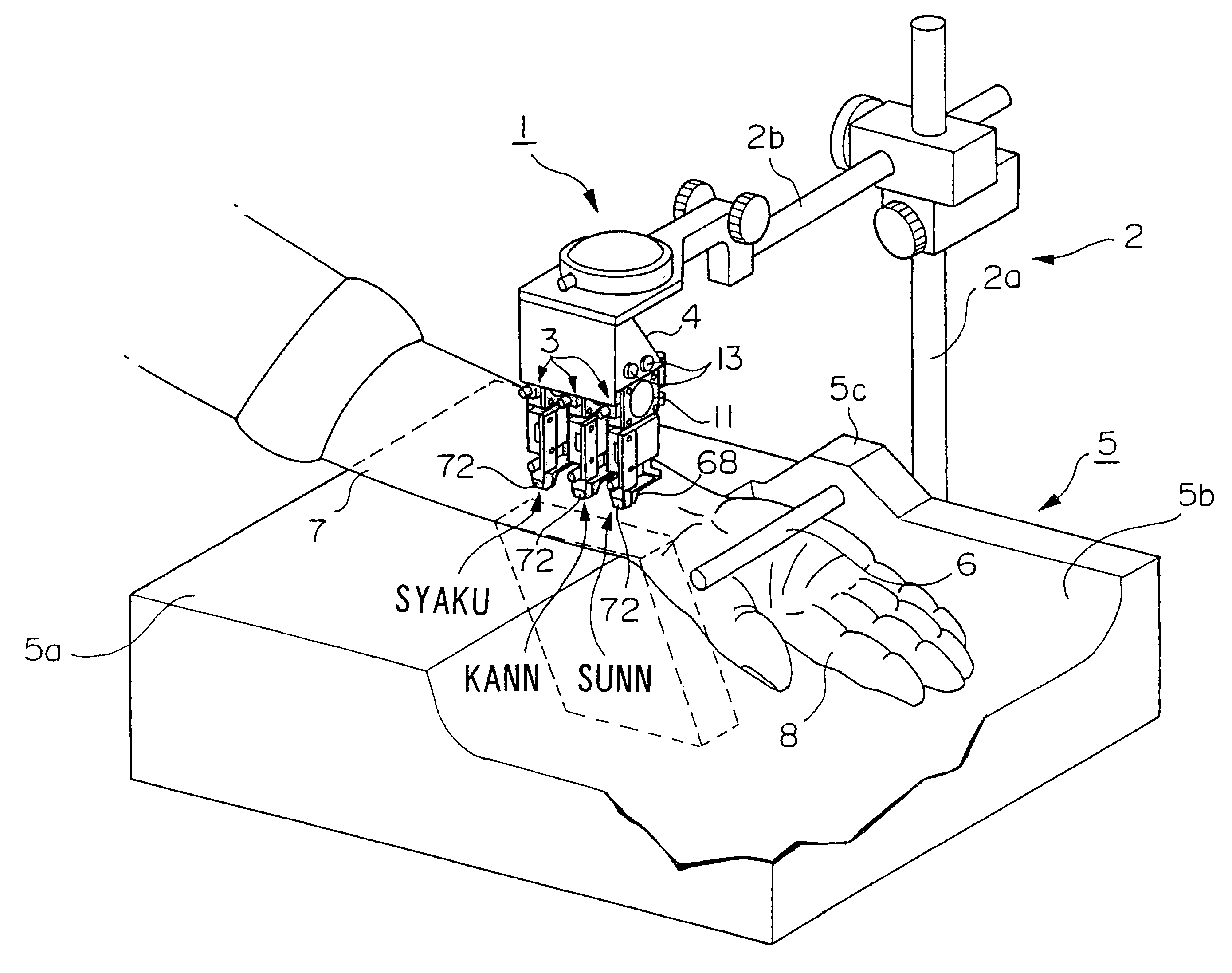
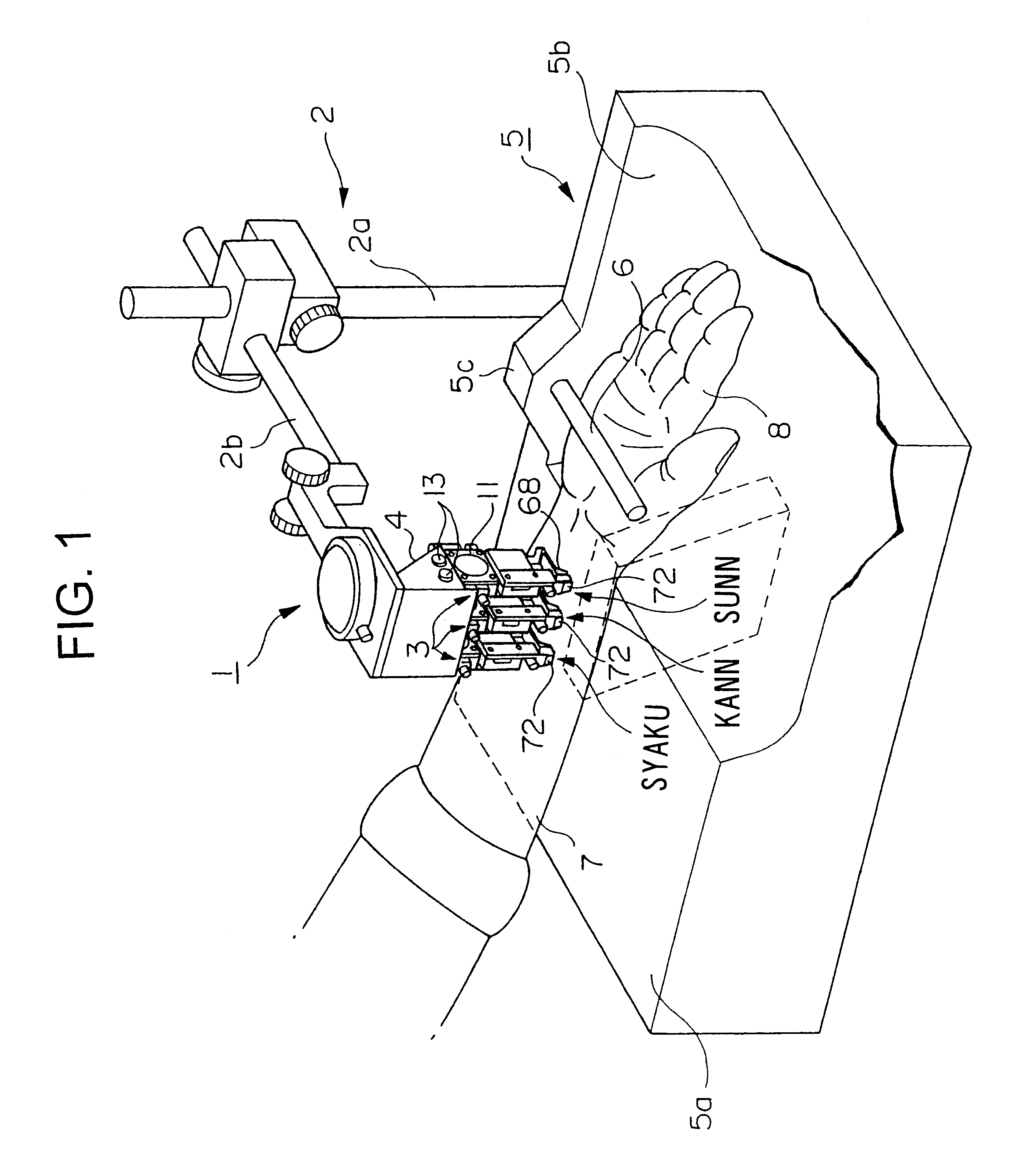
As shown in FIG. 1, a pulse wave measuring device 1 according to a first embodiment of the present invention comprises a stand 2 placed on a flat plane and three pulse wave measuring units 3, which are of the same type as one another, supported by the stand 2. The stand 2 includes a vertically standing shaft 2a, and an arm 2b connected to the shaft 2a. A bracket 4 is arranged at the distal end of the arm 2b.

The height of the proximal end of the arm 2b can be adjusted in relation to the shaft 2a. The arm 2b is rotatable about the shaft 2a, so that the direction of the arm 2b in a horizontal plane can be adjusted. In addition, the arm 2b can be swiveled in a vertical plane, and the direction of the arm 2b in the vertical plane can be adjusted. These adjusting mechanisms are known, so that the description thereof is omitted. By the above-mentioned adjustment of the stand 2, the position of the bracket 4...

second embodiment

the present invention will be described next. FIG. 10 shows important parts of the pulse wave measuring device according to the second embodiment. The pulse wave measuring device also includes three pulse wave measuring units 3, which are almost the same as those in the first embodiment, each of the pulse wave measuring units 3 including the supporting member 10. The second embodiment is different from the first embodiment in the sort of the pulsation measuring sensors provided at the supporting member 10. The structural elements common to the first embodiment are not illustrated in FIG. 10.

As shown in FIG. 10, a beam 110 is secured to the horizontal portion 67 of the first pressing plate 65 in the supporting member 10 in the same fixing manner as of the beam 81 in the first embodiment. The beam 110 comprises a planar supported portion 111, which is a proximal portion secured to the horizontal portion 67; and a bent portion 112, which is perpendicularly bent from the supported porti...

third embodiment

3. Third Embodiment

FIG. 15 shows a pressure measuring device according to third embodiment of the present invention. In this embodiment, a wristband, constituted of band pieces 121a and 121b, of a watch 120 is used for a supporting member for the pressure measuring device. The wrist band pieces 121a and 121b, attached to both ends of a watch body 120a, cooperate to encircle the patient's wrist and are connected by a known hook 122. The circular length of the watch 120 may be adjusted by loosening and fastening of the hook 122, so that the retaining force to the wrist can be adjusted.

The reverse side of the wrist band piece 121a is provided with an optical pulsation measuring sensor 113. Instead of the sensor 113, another type of pressure measuring sensor may be used. By the retaining force of the wrist band pieces 121a and 121b, the pressure measuring sensor or optical pulsation measuring sensor 113 presses the skin over the radial artery 100.

A pair of pressing legs 68 and 72 are al...


PUM


Abstract

A pulse wave measuring device is provided with a plurality of pulse wave measuring units. Each pulse wave measuring unit has a supporting member to which a beam of a pressure measuring device is attached. Contact portions at the distal end of the beam is in contact with the patient's arm, so that piezoelectric elements mounted on the beam measures the stress variation according to pulsation of the patient's radial artery. The supporting member has two pressing legs between which the contact portions of the beam are situated. The distal ends of the pressing legs are also pressed against the patient's arm. The pressing legs are harder than the radial artery. The interval between the pressing legs can be altered by handling a micrometer head. The contact portions are situated back from the distal ends of the pressing legs.

Description

The present invention relates to a device for measuring blood pulse wave, a device for measuring pulsation, and a pressure measuring device.TECHNICAL BACKGROUNDA "bloodpulse wave" is the blood pressure wave, which is pumped out from the heart and propagates through a blood vessel, or the vibration of the blood vessel wall generated by the blood pressure wave. Since various medical information, for example, the vital condition of the heart, can be obtained by detecting and analyzing blood pulse waves, it has been carried out to diagnose blood pulse wave by the diagnostician's sense of touch traditionally in Oriental medicine.More specifically, the diagnostician presses the patient's wrist by his fingers and measures blood pulse wave of the radial artery by the finger's sense of touch in Oriental medicine. Due to the finger pressure, the amplitude of the sensed pulse wave changes, so that the changing characteristic of the amplitude of pulse wave can be a diagnostic parameter in the f...

Claims


Application Information

Patent Timeline
Patent Type & Authority Patents(United States)
IPC IPC(8): A61B5/024
CPCA61B5/02427A61B5/6826A61B5/6838A61B5/6843A61B5/6824
Inventor AMANO, KAZUHIKOHIGUCHI, KOJITAKAHASHI, OSAMUFUNASAKA, TSUKASAMIYAZAKI, HAJIMEYOSHINO, MASAHITO
Owner SEIKO EPSON CORP
Why Eureka
Try Eureka