Apparatus for damping torsional vibrations

a technology of torsional vibration and damping apparatus, which is applied in the direction of couplings, manufacturing tools, slip couplings, etc., can solve the problems of undesirable or even damaging angular movements of such members relative to each other, bulky, complex and expensive, etc., and achieves the effect of less expensive, simple, and more compa

Inactive Publication Date: 2001-04-10
LUK LAMELLEN & KUPPLUNGSBAU BETEILIGUNGS KG
View PDF8 Cites 13 Cited by
  • Summary
  • Abstract
  • Description
  • Claims
  • Application Information

AI Technical Summary

Benefits of technology

An object of the invention is to provide a torsional vibration damping apparatus which is simpler, more compact and less expensive than, but just as reliable and versatile as, heretofore known apparatus.
It has been found that, regardless of whether utilized individually or in any one of a number of different combinations with each other, the aforediscussed features contribute to simplicity, reliability, compactness (both in the direction of the common axis of the primary and secondary flywheels and in a direction at right angles to such axis) and numerous other advantages of the improved torsional vibration damping apparatus as well as of the power train which cooperates with or embodies such apparatus.

Problems solved by technology

More particularly, the invention relates to improvements in torsional vibration damping apparatus of the type wherein rotation of input and output members with each other is desirable (or at least acceptable) but angular movements of such members relative to each other (especially beyond a certain range of such angular movements) are undesirable or even damaging.
A drawback of many presently known torsional vibration damping apparatus is that they are bulky, complex and expensive.
This creates serious problems in the power trains of numerous types of motor vehicles.
Moreover, the assembly of conventional torsional vibration damping apparatus at the locale of use (such as an automobile assembly plant) is often a time-consuming procedure involving numerous welding, riveting, shape-altering, centering and / or other operations which contribute to the cost of the power plant and of the entire motor vehicle.

Method used


Image

  • Apparatus for damping torsional vibrations
  • Apparatus for damping torsional vibrations
  • Apparatus for damping torsional vibrations

Examples


Embodiment Construction

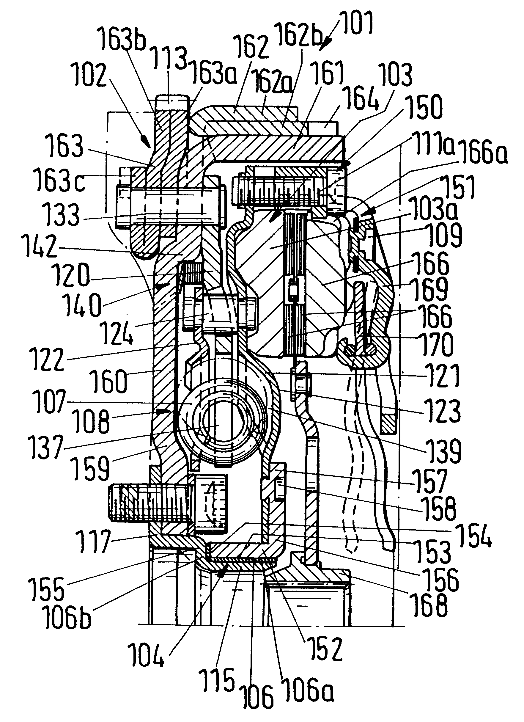
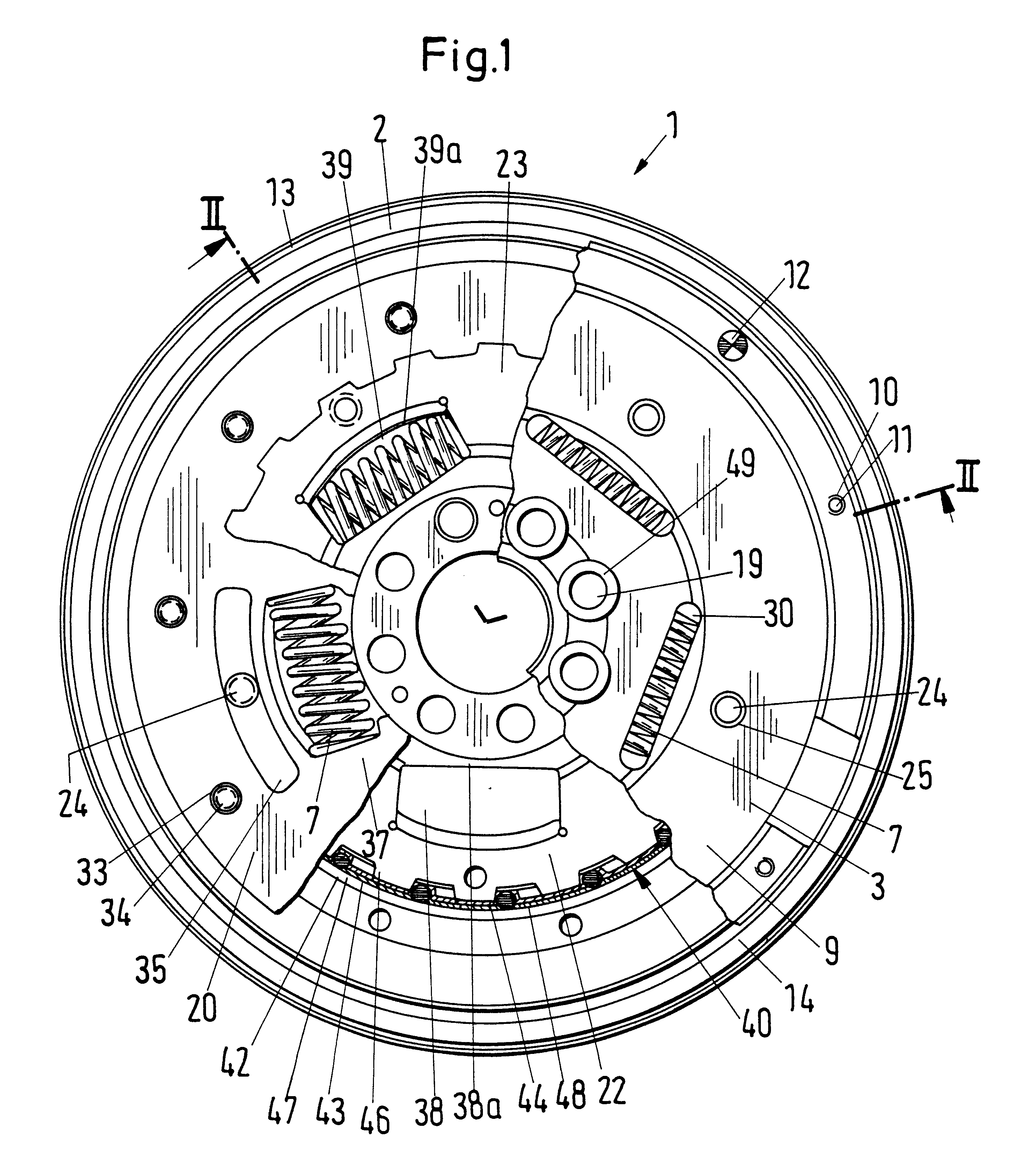
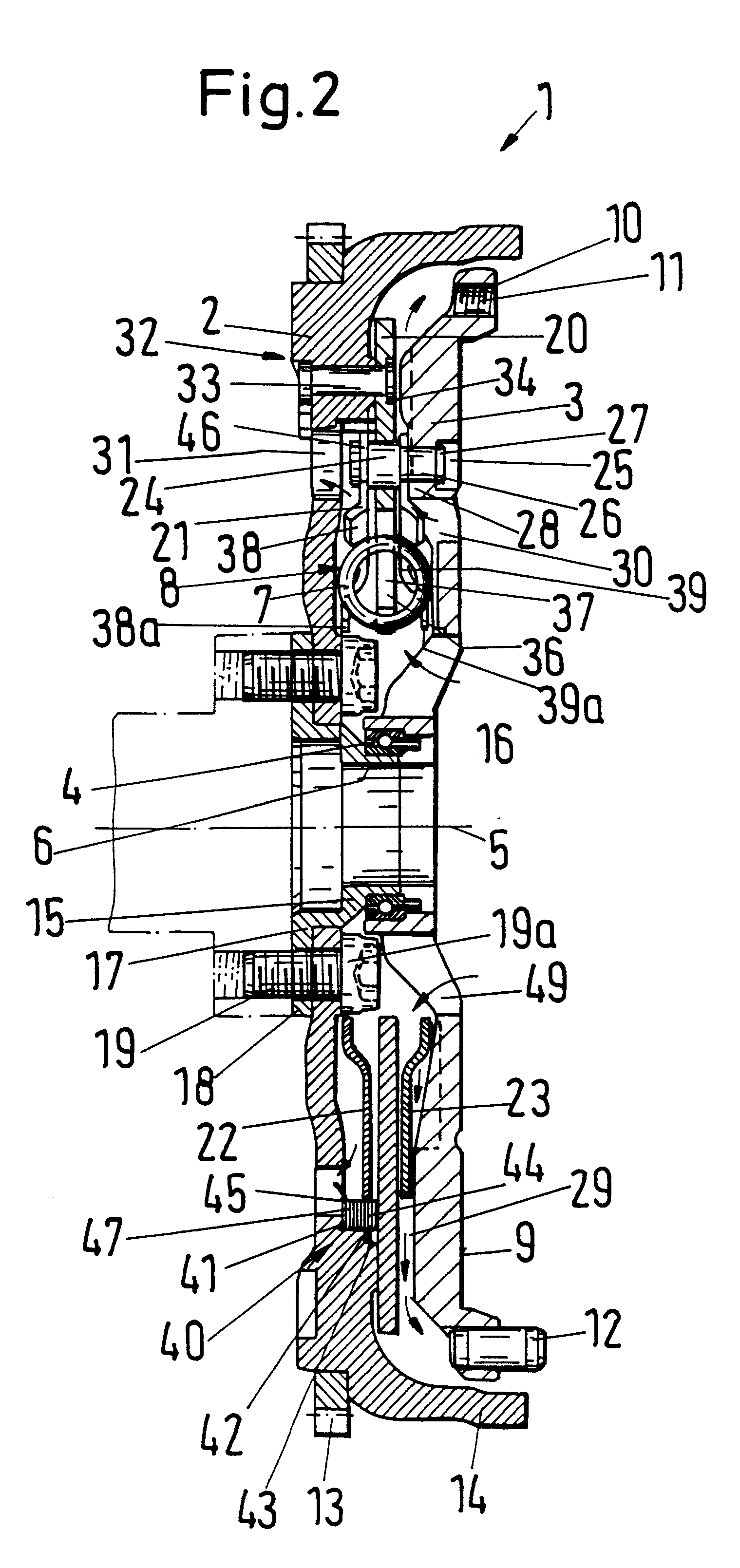
FIGS. 1 and 2 illustrate a portion of a first torsional vibration damping apparatus 1 which is a so-called twin-mass flywheel including input and output members which are rotatable with as well as relative to each other about a common axis 5. The input member of the apparatus 1 comprises a first flywheel or primary flywheel 2, and the output member of the apparatus comprises a second or secondary flywheel 3. The primary flywheel 2 is separably connected or connectable to the rotary output component (such as a camshaft or a crankshaft) of a prime mover, not shown, e.g., an internal combustion engine in a motor vehicle, by suitable fastener or fastening means 19. The illustrated fastening means comprises eight screws or bolts 19 which are parallel to the axis 5, which are located at the same radial distance from such axis, and which are equidistant from each other as seen in the circumferential direction of the primary flywheel 2. A portion of the output component of the prime mover i...


PUM

PropertyMeasurementUnit
thicknessaaaaaaaaaa
angleaaaaaaaaaa
angleaaaaaaaaaa

Abstract

Apparatus for damping torsional vibrations in the power train of a motor vehicle has two coaxial flywheels one of which is driven by the engine and the other of which can transmit torque to the input shaft of a transmission by way of a friction clutch. The flywheels are rotatable relative to each other against the resistance of a damper. Certain features of the apparatus reside in the dimensioning and distribution of its parts in the radial and axial directions of the flywheels to reduce the dimensions of the apparatus. The torque transmitting connection between at least one pair of neighboring rotary parts of the apparatus employs a slip clutch which yields when the applied torque exceeds a certain value. An intermittently or continuously active hysteresis device is utilized to operate in parallel with the energy storing springs of the damper.

Description

The present invention relates to improvements in apparatus for damping torsional vibrations. More particularly, the invention relates to improvements in torsional vibration damping apparatus of the type wherein rotation of input and output members with each other is desirable (or at least acceptable) but angular movements of such members relative to each other (especially beyond a certain range of such angular movements) are undesirable or even damaging.It is known to utilize torsional vibration damping apparatus in the power trains of motor vehicles, e.g., between the rotary output component of an internal combustion engine (or another suitable prime mover) and the input component (e.g., a flywheel) of an automated or manually engageable and disengageable friction clutch which, in turn, serves to transmit variable torque to the rotary input component of a manually shiftable or automated or automatic variable-speed transmission.A drawback of many presently known torsional vibration ...

Claims


Application Information

Patent Timeline
Patent Type & Authority Patents(United States)
IPC IPC(8): F16F15/139F16F15/131B23P15/00B23P11/02F16F15/134F16F15/16F16F15/30F16F15/315
CPCF16F15/13142F16F15/1315F16F15/13171F16F15/139F16F15/13178Y10T29/497Y10T29/49481F16D7/025F16F15/13121F16D2013/703F16D13/50
Inventor JACKEL, JOHANNNIESS, DANIEL
Owner LUK LAMELLEN & KUPPLUNGSBAU BETEILIGUNGS KG
Why Eureka
Try Eureka