Electrohydraulic pressure wave projectors

a technology of electrohydraulic pressure wave and projector, which is applied in the direction of seismology for waterlogging, dislodging machines, instruments, etc., can solve the problems of not being able to efficiently create high-energy waves, difficulty in efficiently loading energy into salt water, and difficulty in efficiently loading electrical energy into any type of underwater plasma

Inactive Publication Date: 2001-04-10
SDG LLC
View PDF4 Cites 119 Cited by
  • Summary
  • Abstract
  • Description
  • Claims
  • Application Information

AI Technical Summary

Problems solved by technology

However, it has not heretofore been possible to create efficient high energy waves.
The primary reasons for this are the difficulty with efficiently loading energy into salt water and the difficulty of efficiently loading electrical energy into any type of underwater plasma.
However, electrode life and the capability of effici...

Method used


Image

  • Electrohydraulic pressure wave projectors
  • Electrohydraulic pressure wave projectors
  • Electrohydraulic pressure wave projectors

Examples


Embodiment Construction

)

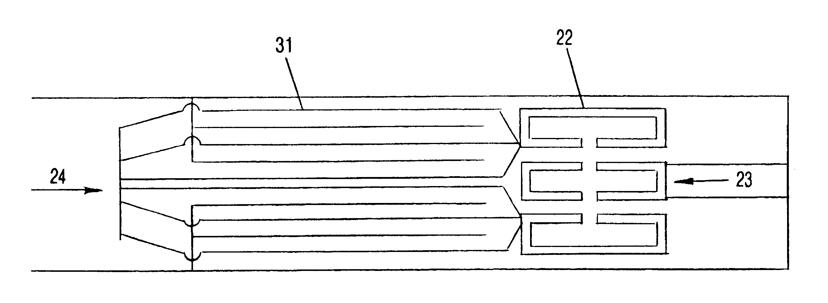
The present invention is an apparatus for and method of controlling the source impedance for an underwater plasma in order to efficiently transfer electrical energy to the plasma. This invention overcomes the weaknesses in power transfer efficiency of prior art underwater spark pressure wave projector systems. The invention comprises packaging the pulsed power components, especially the capacitor, in close proximity (preferably within approximately one meter, more preferably within approximately 50 cm, and most preferably within approximately 10 cm) to the electrode gap or gaps in order to minimize stray inductance and to maximize power transfer to the underwater plasma. A low inductance switch capable of passing high current connects the energy storage device to the electrodes. In one embodiment, the switch is incorporated into the electrode gap and a low inductance connector connects the energy storage device to the electrode / switch array.

One approach for enhancing breakdown volt...


PUM


Abstract

A projector (10) for creating electrohydraulic acoustic and pressure waves comprising an energy source (21) (such as a capacitor) within approximately one meter of an electrode array (23). Larger projectors may be formed by arraying the projectors, and still larger projectors by arraying them.

Description

1. Field of the InventionTechnical FieldThe present invention relates to electrohydraulic projectors, particularly those utilizing an electrical plasma in a liquid to create acoustic, pressure, and shock waves, and methods for efficiently coupling the electrical current to the plasma.2. Background ArtThe underwater plasma (10) physical processes at issue are shown in FIG. 1. When high voltage is impressed across two electrodes (11) immersed in water (12) or some other liquid, and the electric field (voltage divided by the electrode separation and modified for the shape of electrodes) is above the breakdown electric field of the water (12), then a conducting plasma channel (10) forms between the two electrodes (11). Especially if significant current is passed through the conducting channel (10), a number of important events occur. A zone of steam or vapor is formed around the plasma channel (10), and this bubble (13) of steam (14) propagates outward from the channel (10) at a rate th...

Claims


Application Information

Patent Timeline
IPC IPC(8): H04R23/00
CPCE21B7/007H04R23/00
Inventor MOENY, WILLIAM M.WINSOR, NIELS K.
Owner SDG LLC
Why Eureka
Try Eureka