Detecting fields with a single-pass, dual-amplitude-mode scanning force microscope

a scanning force microscope and scanning force technology, applied in the direction of mechanical measurement arrangements, mechanical roughness/irregularity measurements, instruments, etc., can solve the problem of not necessarily reflecting, second-harmonic oscillation of the cantilever, and the difficulty of measuring these quasi-static deflections in a manner providing an accurate depiction of the underlying electric or magnetic field

Inactive Publication Date: 2001-04-24
INT BUSINESS MASCH CORP
View PDF13 Cites 27 Cited by
  • Summary
  • Abstract
  • Description
  • Claims
  • Application Information

AI Technical Summary

Benefits of technology

A second objective of the present invention is to provide a method for reducing the distance between the center of vibration of a probe during the measurement of a magnetic or electric field, so that the spatial resolution and signal-to-noise ratio of such a measurement can be improved.

Problems solved by technology

However, the contours of the constant-force gradient measured in this way do not necessarily reflect only a level of magnetic contrast, due to the dependence of the non-magnetic forces on the distance between the probe tip and the sample surface.
With this technique, for example, adding an AC modulation signal to the applied DC bias causes a second-harmonic oscillation of the cantilever.
A disadvantage of this method lies in the difficulty of measuring these quasi-static deflections in a manner providing an accurate depiction of the underlying electric or magnetic field.
Such deflections are not easily measured with the accuracy available through the use of AC methods depending on changes in the amplitude of vibrations occurring at a frequency near the resonate frequency of the cantilever.

Method used


Image

  • Detecting fields with a single-pass, dual-amplitude-mode scanning force microscope
  • Detecting fields with a single-pass, dual-amplitude-mode scanning force microscope
  • Detecting fields with a single-pass, dual-amplitude-mode scanning force microscope

Examples


Embodiment Construction

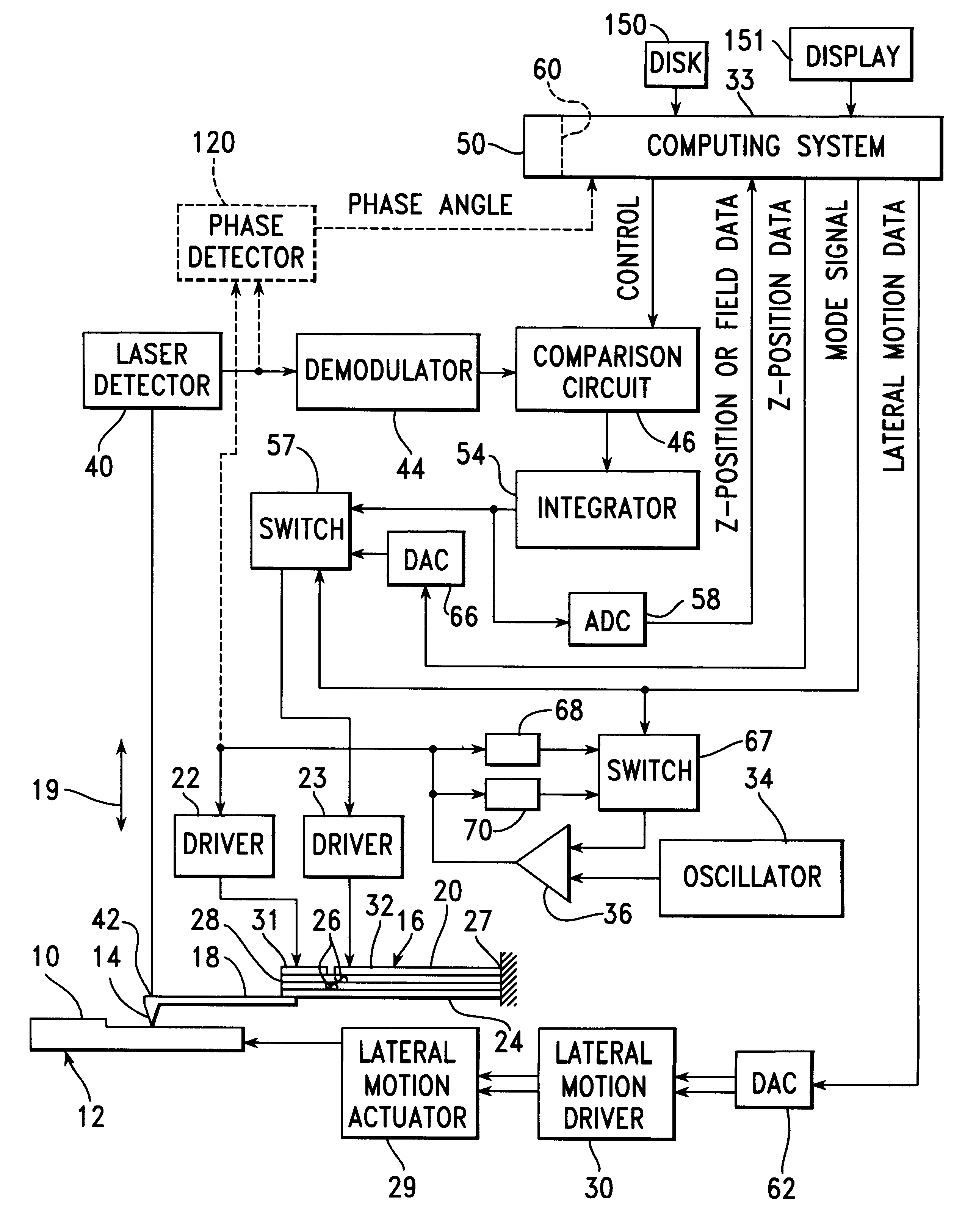
FIG. 1 is a schematic view of apparatus built in accordance with the present invention. In this apparatus, both the topographical characteristics of a surface 10 of a sample 12 and the magnetic field extending outward from the surface 10 are measured by means of a probe tip 14, which is attached to a bimorph piezoelectric actuator 16 through a cantilever 18. The probe tip 14 is moved into and out of engagement with the sample surface 10, in the directions of arrow 19, as voltage signals are applied to upper electrode 20 of the bimorph piezoelectric actuator by means of driver circuits 22, 23, with the lower electrode 24 thereof being maintained at electrical ground. The actuator 16 includes a pair of strips 26 of piezoelectric material extending between the electrodes 20, 24. The proximal end 27 of the actuator 16 is clamped, while the distal end 28 thereof is fastened to the cantilever 18. The sample 12 is moved in a pattern of lateral scanning motion parallel to the surface 10 by ...


PUM

PropertyMeasurementUnit
forcesaaaaaaaaaa
displacementaaaaaaaaaa
resonant frequencyaaaaaaaaaa

Abstract

A scanning probe microscope operates in the manner of an atomic force microscope during intermittent periods of scanning motion, in which a sample surface is driven so that a scan line on the surface is moved past a probe tip being vibrated in engagement with the surface. Between these intermittent periods of scanning motion, the vibrating probe tip is moved out of engagement with the sample surface, so that the amplitude and phase shift of probe tip vibrations are determined by the gradient of a force field extending outward from the sample surface. Such a force field is established when the probe tip is attracted by, or repelled from, a magnetic or electric field at or near the sample surface. For each sample point, the system stores data representing the height of the sample surface and the force field.

Description

1. Field of the InventionThis invention relates to a method for measuring magnetic or electric fields within a sample material and, more particularly, to a method using a scanning force microscope to track the topography of the surface so that such fields occurring close to the material surface are accurately measured at a small, constant distance from the surface.2. Background InformationThe measurement of a magnetic or electric field occurring within a sample material, from a measurement point traversing the surface of the material at a very close spacing beyond this surface, has been a subject of an ongoing effort by scanning probe microscopy researchers for several years. A measurement process of this type requires that a probe sensitive to magnetic or electric fields must be moved in a direction perpendicular to the sample surface during the traversing, or scanning process, so that the probe tracks the topography of the sample surface without contacting it. Moving the probe in ...

Claims


Application Information

Patent Timeline
Patent Type & Authority Patents(United States)
IPC IPC(8): G01R29/08G01R31/303G01R31/28G01B21/30G01N37/00G01B7/34G01Q60/34G01R33/10G01R33/12
CPCB82Y35/00G01Q60/30G01Q60/34G01R29/0878G01R31/303Y10S977/851Y10S977/852
Inventor CHEN, DONGFLECHA, EDWINHAMMOND, JAMES MICHAELROESSLER, KENNETH GILBERT
Owner INT BUSINESS MASCH CORP
Why Eureka
Try Eureka