Carrier frequency measuring method and apparatus

a frequency measurement and carrier technology, applied in the direction of weighing apparatus, amplifiers, transmission, etc., can solve the problems of difficult to achieve an accurate calibration and evaluation of measurement, and difficulties in such measuring methods

Inactive Publication Date: 2001-04-24
CARL SCHENCK AG
View PDF9 Cites 20 Cited by
  • Summary
  • Abstract
  • Description
  • Claims
  • Application Information

AI Technical Summary

Problems solved by technology

However, difficulties arise in such measuring methods because the strain gage transducer bridge circuit typically outputs a measurement voltage of only a few millivolts, even under maximum load, whereby this small measurement voltage must be amplified in corresponding measuring amplifiers for further processing, evaluation and transmission.
The demodulation carried out before the analog-to-digital conversion is typically carried out by me

Method used


Image

  • Carrier frequency measuring method and apparatus
  • Carrier frequency measuring method and apparatus
  • Carrier frequency measuring method and apparatus

Examples


Embodiment Construction

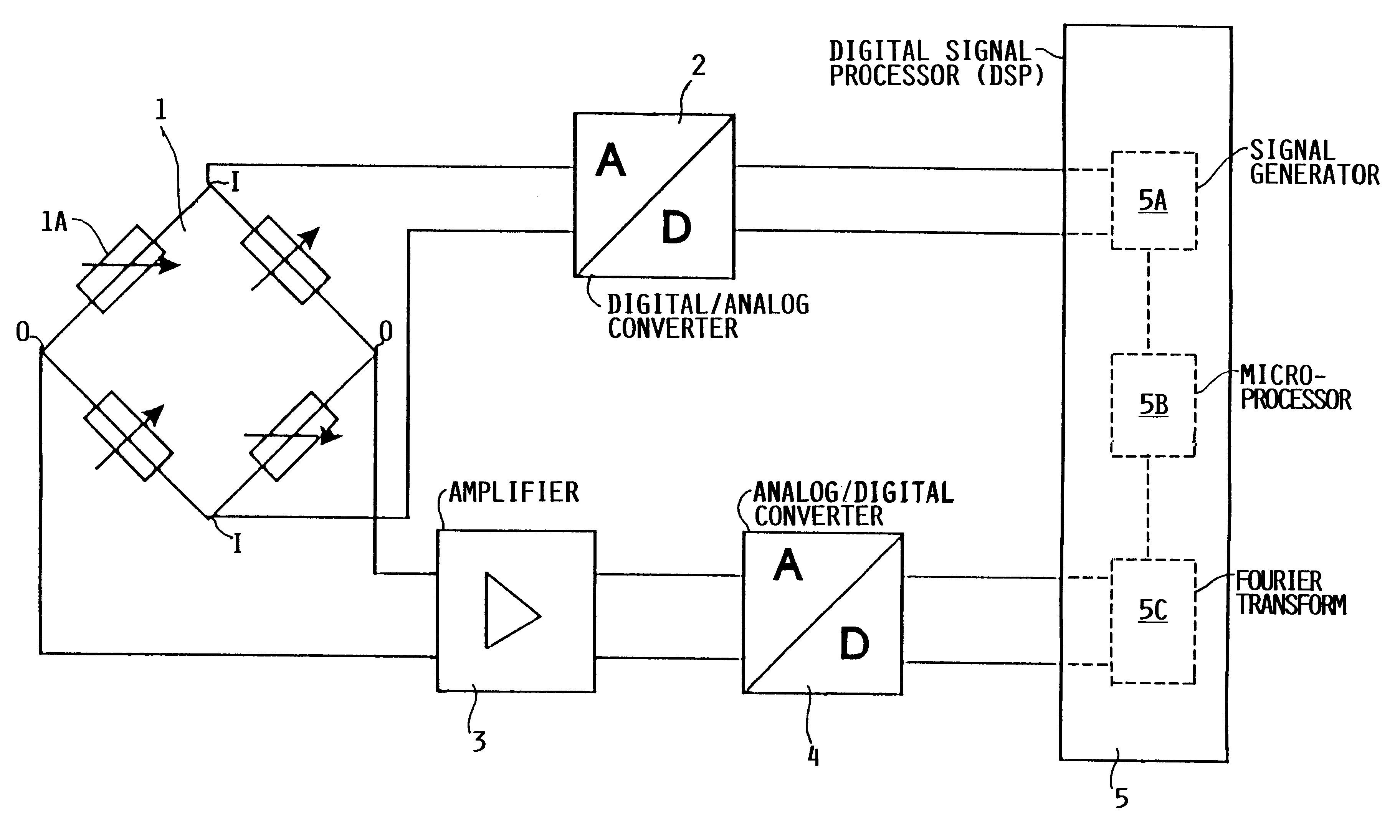
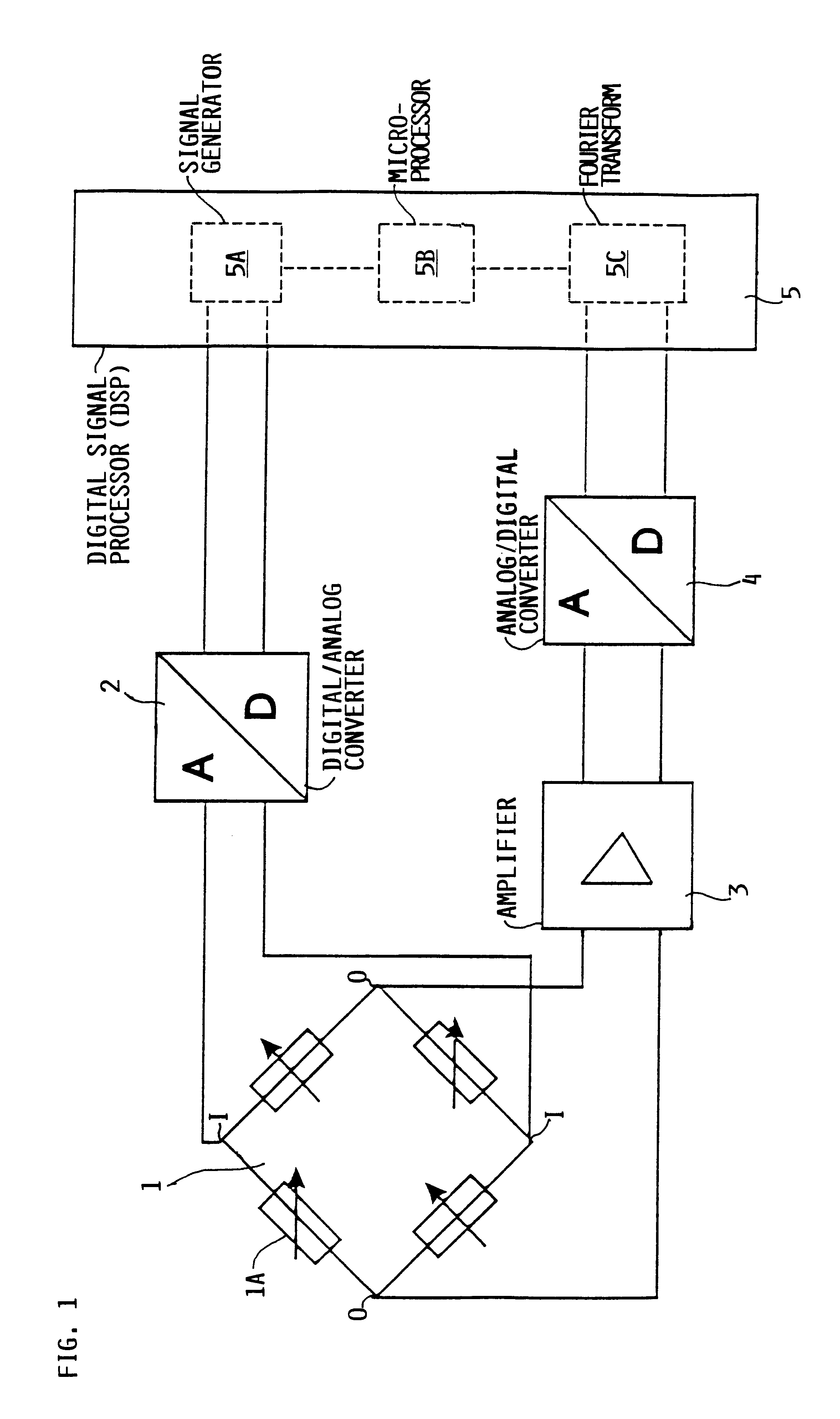
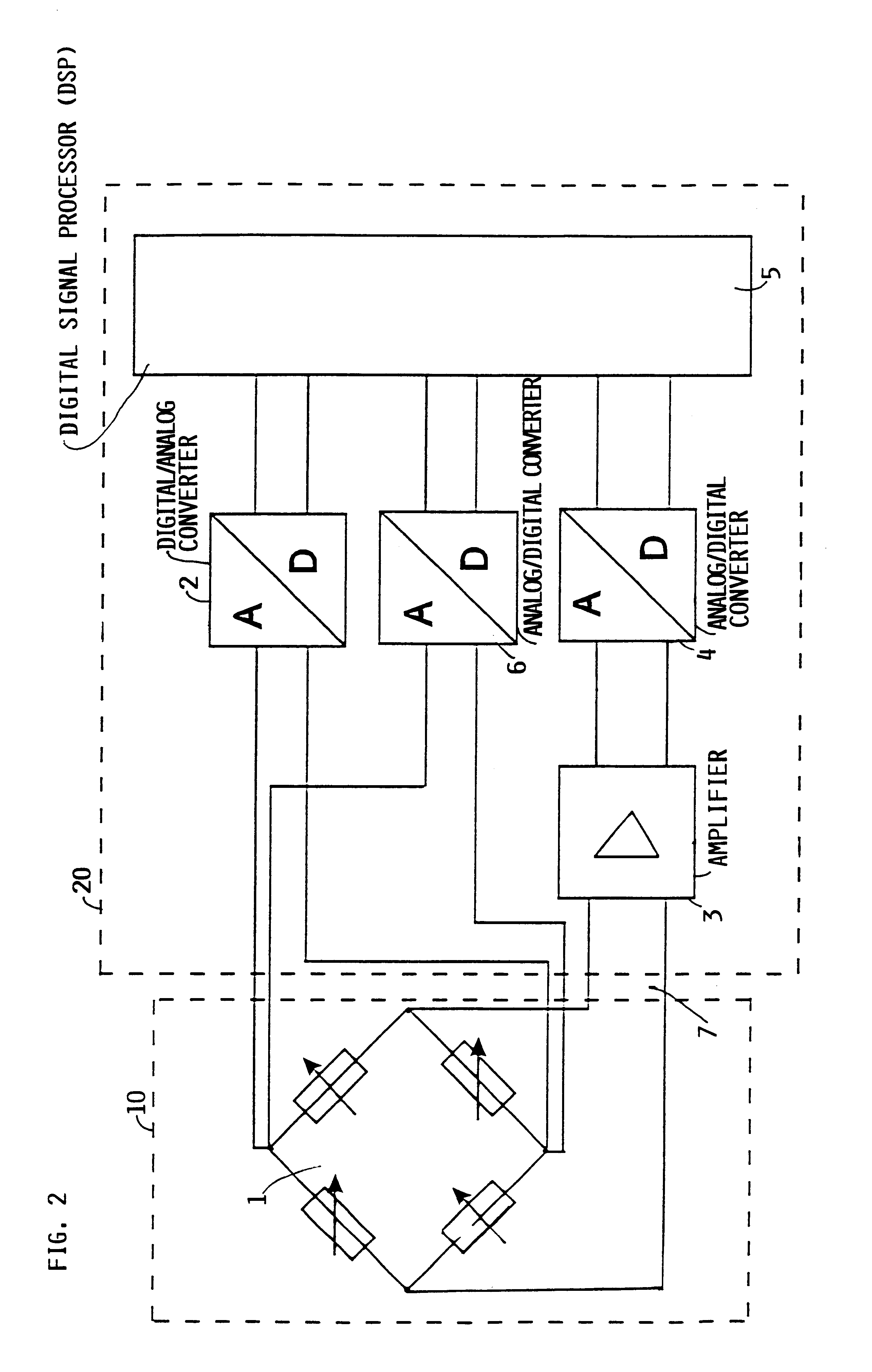
FIG. 1 schematically shows the construction of a carrier frequency measuring circuit according to the invention, in which a digital signal processor circuit 5 is connected to a digital input of a digital-to-analog converter 2, which in turn provides a carrier frequency to the inputs I of a transducer bridge circuit 1. The bridge circuit 1 modulates the carrier frequency with a measurement value. The resulting modulated signal is provided from the outputs O of the bridge circuit 1, and is then amplified, digitalized and delivered back to the digital signal processor circuit 5 for evaluation. The details of this circuit and its operation will now be described.

The digital signal processor circuit (DSP) 5 includes a signal generator 5A, a microprocessor 5B, and a Fourier transform circuit or module 5C. These subcomponents can all be integrated or incorporated in an integrated circuit and particularly a microprocessor circuit. The signal generator 5A generates a digital carrier frequency...


PUM


Abstract

In a signal measuring method and apparatus, a digital signal processor (5) including a digital signal generator (5A) generates a digital signal, which is converted by a digital-to-analog converter (2) into a sinusoidal analog signal that is applied as a supply voltage to the transducers, such as load cell strain gages arranged in a bridge circuit (1). The analog supply voltage signal is modulated by the measurement voltage in the bridge circuit (1). The resulting modulated signal is amplified if necessary in an amplifier (3), and is then digitalized in an analog-to-digital converter (4) operating with a sampling frequency at least twice the carrier frequency and preferably corresponding to a whole number multiple thereof. The digital signal processor (5) carries out a Fourier transform of the digitalized signal to calculate the magnitude and phase of the measurement voltage, which may then be used for the complex calculation of zero point compensations and adjustment calibrations.

Description

PRIORITY CLAIMThis application is based on and claims the priority under 35 U.S.C. .sctn.119 of German Patent Application 197 22 077.0, filed on May 27, 1997.The invention relates to a method and apparatus for measuring the output of a sensor or pick-up transducer in a bridge circuit using a carrier frequency.BACKGROUND INFORMATIONVarious methods are known for measuring or evaluating the measurement output of foil strain gage transducers arranged in a bridge circuit. However, difficulties arise in such measuring methods because the strain gage transducer bridge circuit typically outputs a measurement voltage of only a few millivolts, even under maximum load, whereby this small measurement voltage must be amplified in corresponding measuring amplifiers for further processing, evaluation and transmission. In order that these analog measurement values can be transmitted and evaluated in microprocessor circuits with the lowest possible distortion or interference, the analog output signa...

Claims


Application Information

Patent Timeline
IPC IPC(8): G01G3/00G01G3/147
CPCG01G3/147
Inventor RAFFIUS, GERHARDPITZ, JUERGENSONNENSCHEIN, ROLAND
Owner CARL SCHENCK AG
Why Eureka
Try Eureka