
Thermal connection system for modular computer system components

a technology of modular computer system and connection system, which is applied in the field of computer systems, can solve the problems of destroying the structure of the chip, affecting the operation of the chip, and heat dissipation, so as to reduce the manufacturing effort, reduce the size, and easy to add and remove.

Inactive Publication Date: 2001-05-08
DELL PROD LP
View PDF23 Cites 38 Cited by
  • Summary
  • Abstract
  • Description
  • Claims
  • Application Information

AI Technical Summary

Benefits of technology

As a result of the above-described thermal connection system, components are thermally connected to one or more arterial heat conductors, rather than directly to the heat sink. The thermal connectors permit components to be easily added and removed. The connector provides a self-aligned connection, which reduces manufacturing effort.
The design provides for a central cooling location for all components, and relaxes constraints related to the need for cooling devices immediately proximate to the components to be cooled. This permits even the most critical components, such as processor and memory units, to be reduced in size, more tightly packed, and more easily serviced.

Problems solved by technology

Heat dissipation is a major issue in the design and operation of semiconductor devices ("chips").
Too much heat can destroy the structure of a chip and affect its operation.
The tight packing of chips in today's computer systems makes them even more vulnerable to damage from heat.
Both fans and heat sinks present design challenges because they must be placed where they will be effective, yet not add bulk to the computer system.
Also, electrical design considerations result in competition between electrical components and thermal components for the same "real estate".
However, the addition of heat pipes has often resulted in increased manufacturing complexity and reduced serviceability after manufacture, because of the connections required for the heat pipes.

Method used


Image

  • Thermal connection system for modular computer system components
  • Thermal connection system for modular computer system components
  • Thermal connection system for modular computer system components

Examples


Embodiment Construction

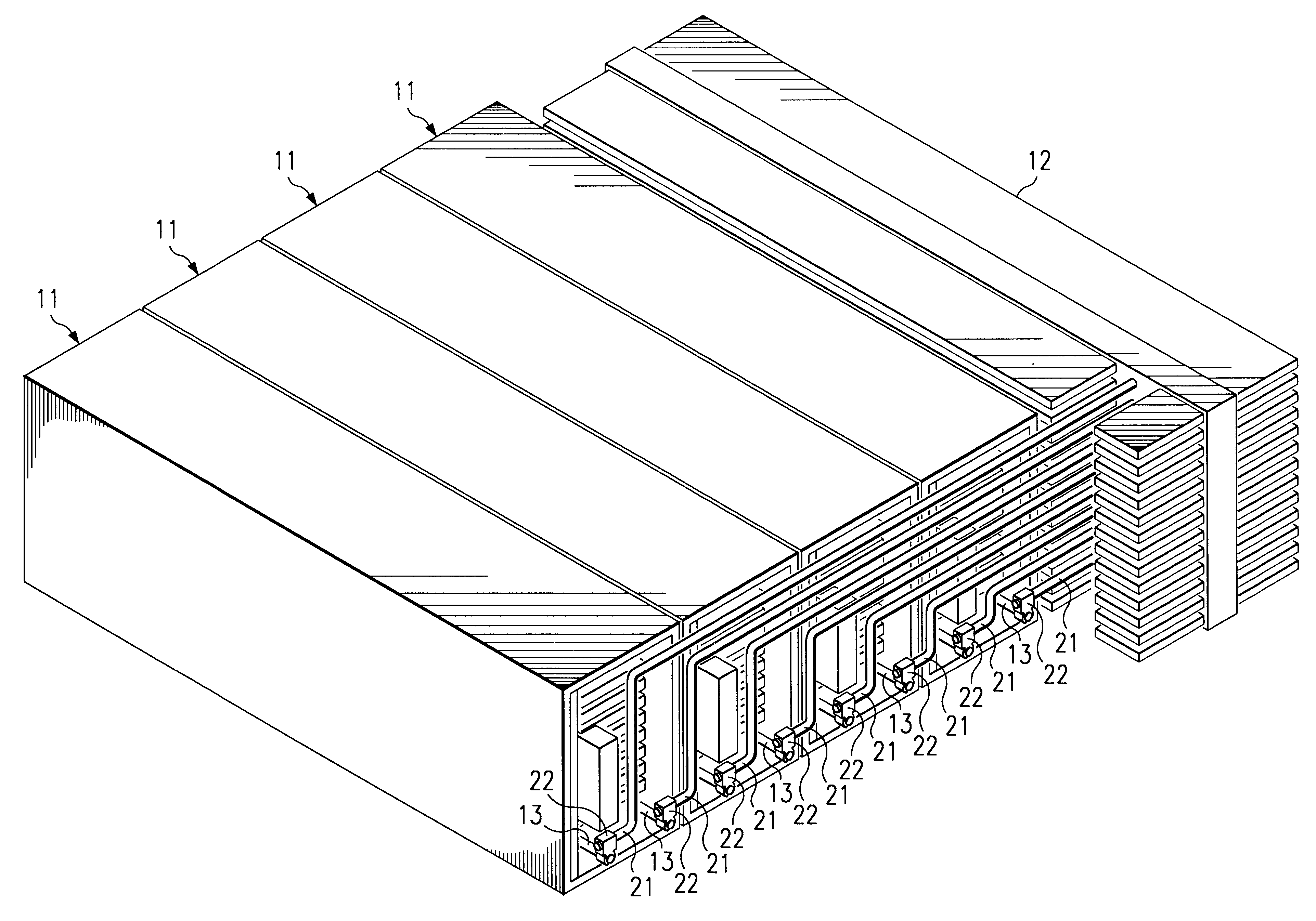
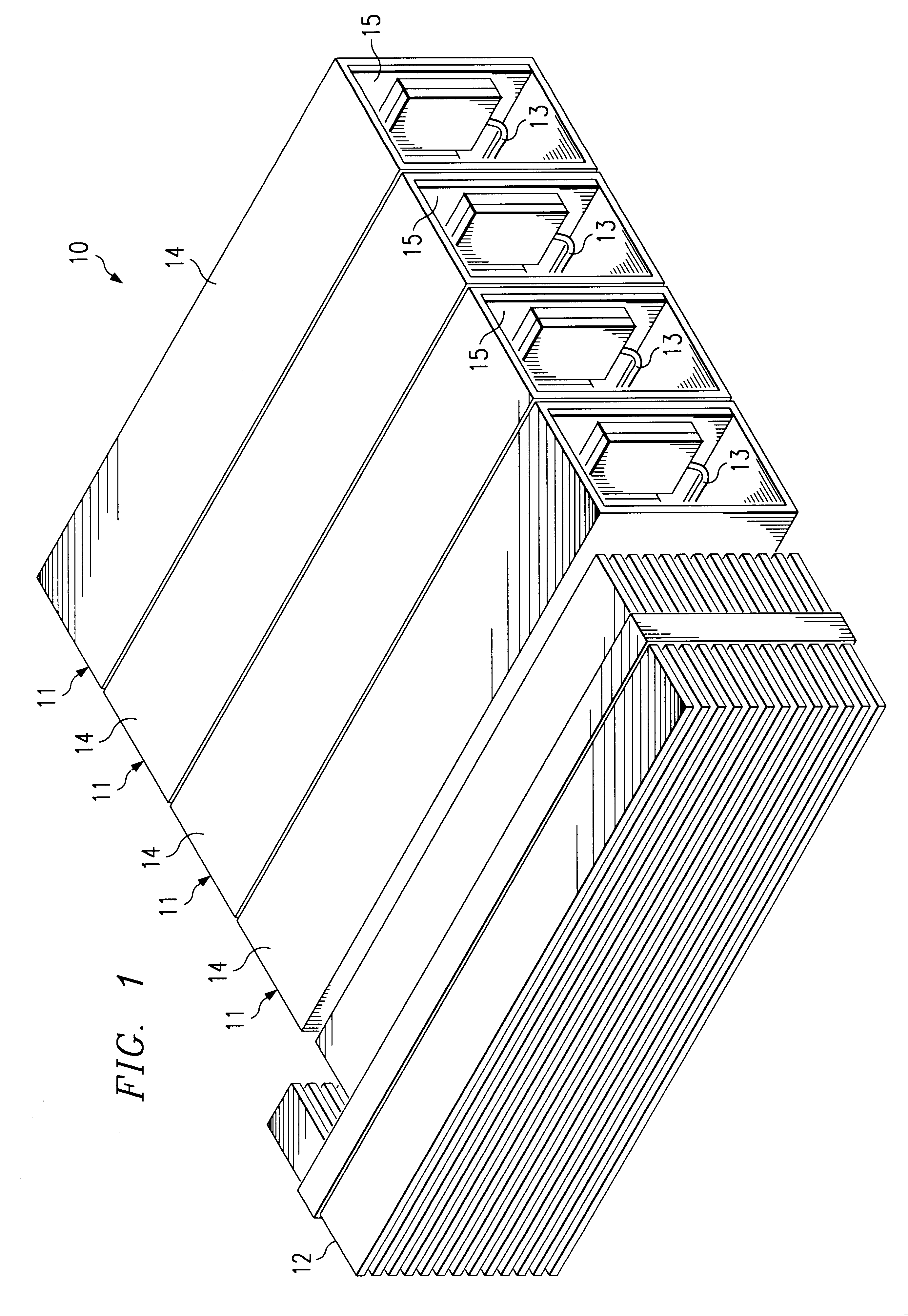
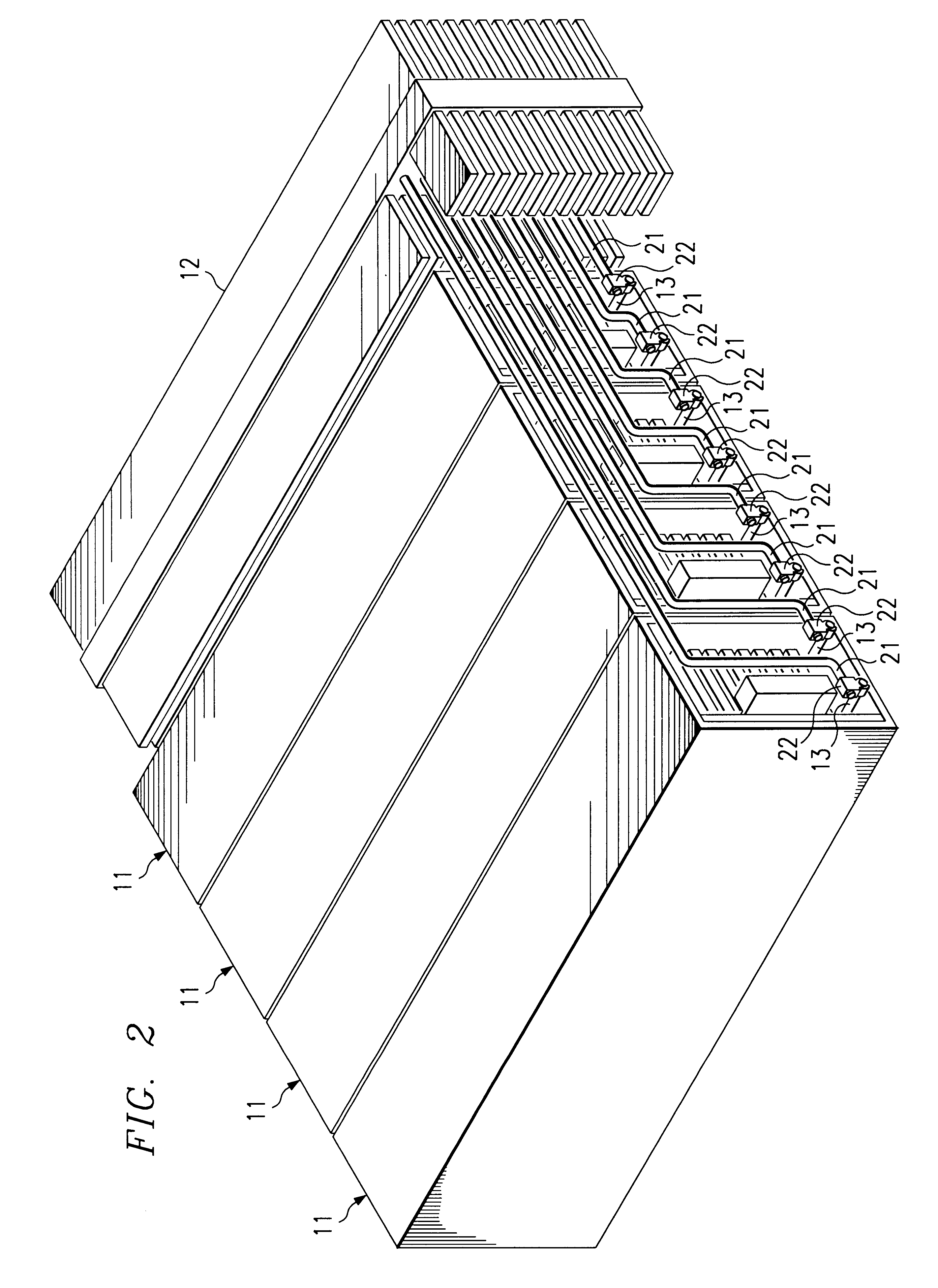
FIGS. 1 and 2 are front and rear perspective views, respectively, of a digital processing unit 10, comprised of a number of modules 11 and a heat sink 12. In the example of this description, processing assembly 10 has four modules, but the number of modules is not significant to the invention.

Modules 11 are designed for use in a computer system, and may contain any type of integrated circuitry associated with digital processing, controlling, or micro-electromechanics. For example, processing unit 10 may function as the system unit of a computer, akin to a "system board" or an "expansion board". The term "digital processing" is used herein in a broad sense to include any function associated with a computing system--processing unit 10 need not necessarily contain any module 11 having a processor. Although not illustrated, each module 11 typically has appropriate electrical connections to a bus or other data communications link.

Each module 11 has at least one heat conductor 13 that ext...


PUM


Abstract

A method and system of thermally connecting internal components of a computer system to a heat sink. The components are arranged as modular units, each having at least one component heat conductor extending from it. For each component heat conductor, an arterial heat conductor extends from the heat sink. Each module heat conductor is attached orthogonally to its associated arterial heat conductor, using a special thermal connector.

Description

TECHNICAL FIELDThis invention relates to computer systems, and more particularly to devices for transferring heat away from internal computer system components.BACKGROUNDHeat dissipation is a major issue in the design and operation of semiconductor devices ("chips"). Too much heat can destroy the structure of a chip and affect its operation. The tight packing of chips in today's computer systems makes them even more vulnerable to damage from heat.One approach to avoiding overheating is with the use of an active cooling device, such as a fan. Conventionally, a fan is a component of the computer system, contained in the computer chassis.Another approach to avoiding overheating is the use of a passive cooling device, such as a heatsink. A heatsink provides a surface area from which heat can radiate. Many heatsinks have fins or some other geometry that increases their surface area. They are made from a material having good thermal conduction, such as aluminum. Some computers are designe...

Claims


Application Information

Patent Timeline
IPC IPC(8): G06F1/20H05K7/20
CPCG06F1/20
Inventor HOSS, SHAWN P.MOSS, DAVID L.
Owner DELL PROD LP
Learn More