By using at least one piezoelectric
actuator for actuating the servo-flap of the inventive airfoil member, the operational flexibility of the airfoil member is increased. A piezoelectric
actuator may comprise a piezoelectric
solid state element stack made up of a plurality of separate piezoelectric material
layers stacked one on top of another in a lengthwise direction of the overall
solid state structure, and respective electrodes interposed therebetween for contacting the piezoelectric
layers. Respective alternating ones of the electrodes can be selectively energized with
voltage of opposite polarity in order to induce the piezoelectric
layers to expand in the lengthwise direction and contract in the crosswise direction of the stack. Due to the stacked arrangement, the electrically induced length variations or strains of the individual piezoelectric layers are added to each other, whereby the total achievable working
stroke of the stacked
solid state structure is considerably increased. Such actuators are characterized by a high actuating speed, a high applied force, and a great resolution of the actuating displacement. Moreover, such piezoelectric actuator systems are compact, light in weight and not subject to a mechanical tilting displacement or jamming of the actuating components, since the actuating movement is generated from within the
solid state bodies.
Advantageously, the
piezoelectric actuators and the entire actuating
system may be arranged inside the airfoil member so that the
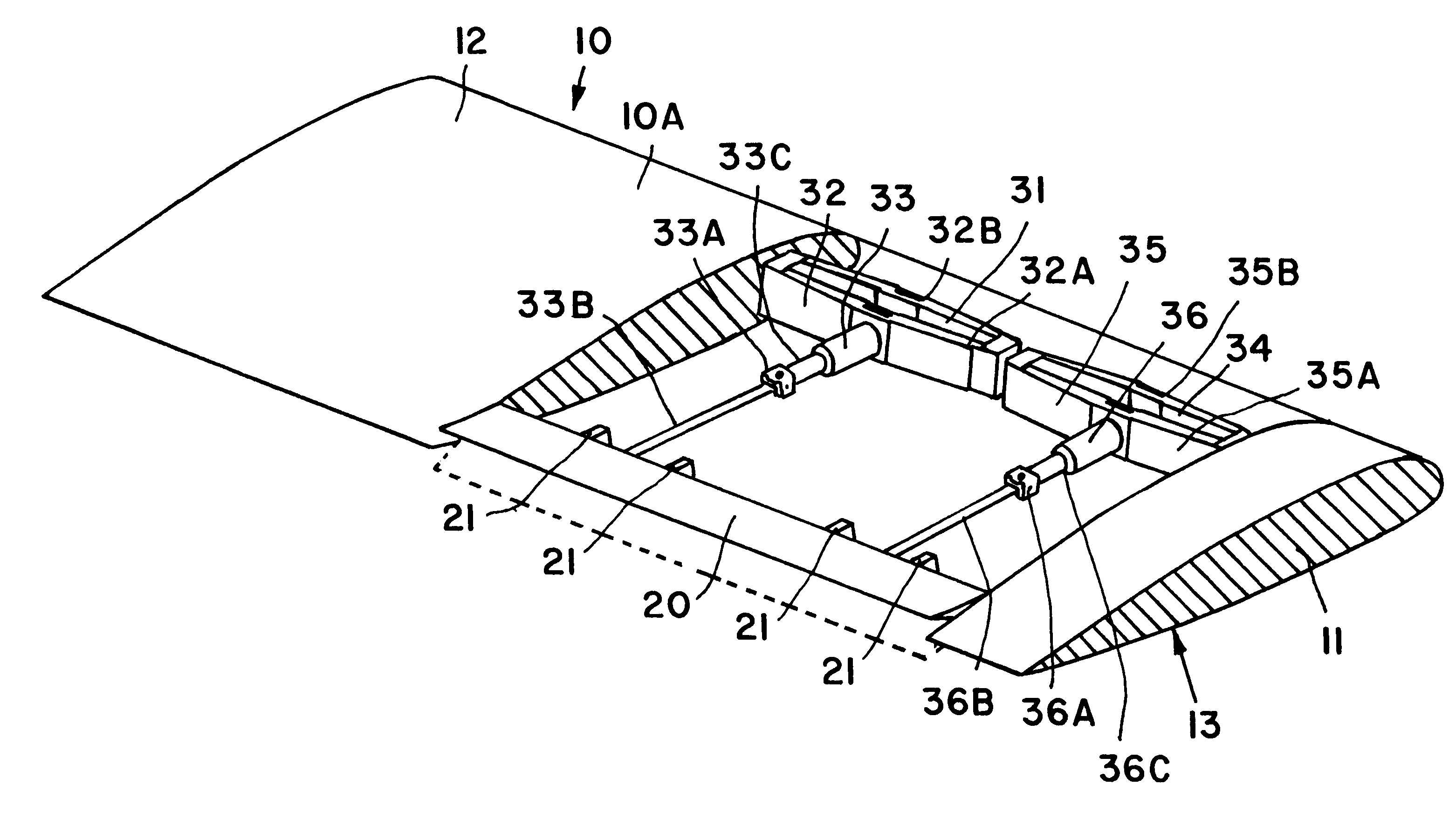
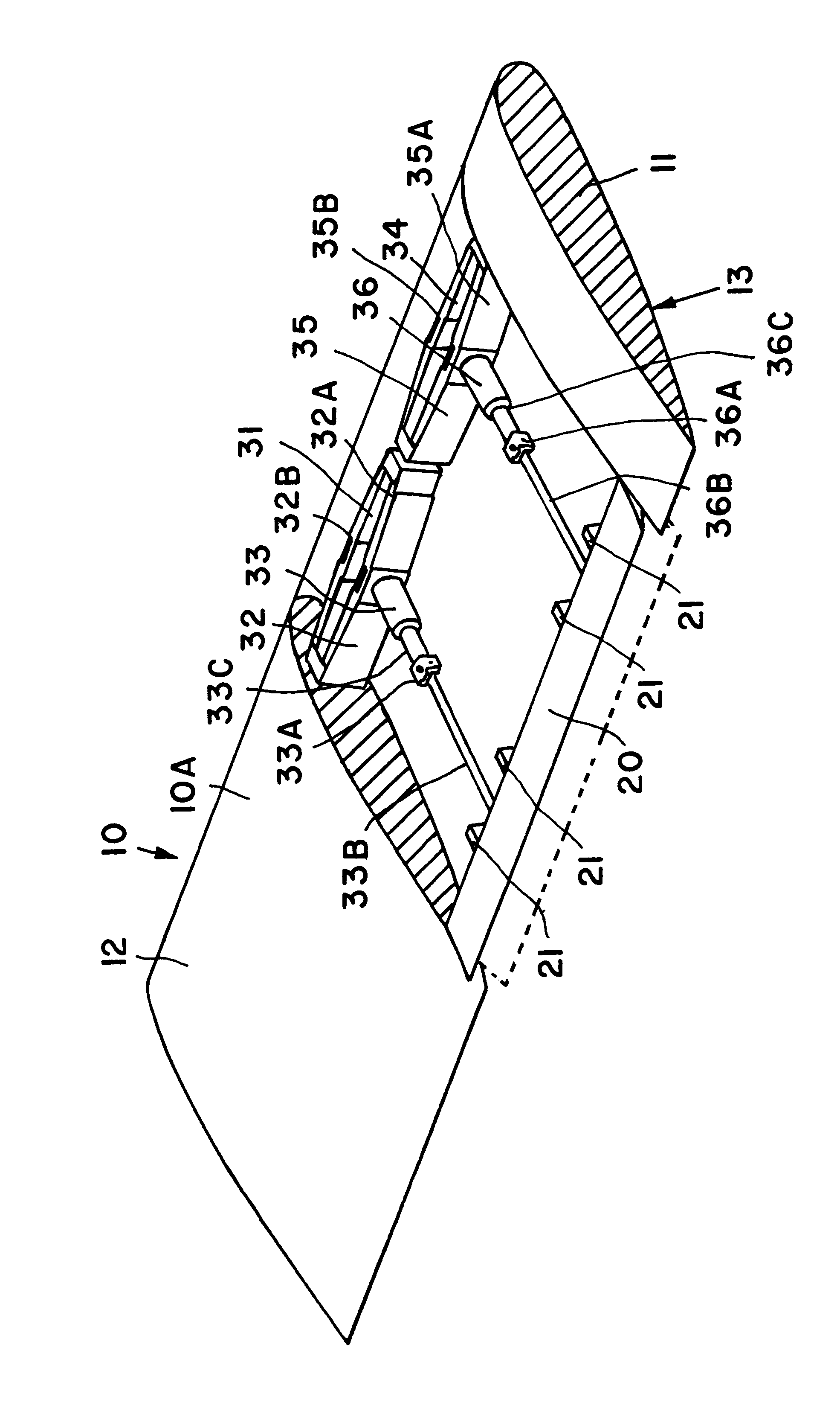
aerodynamics of the airfoil member are not disadvantageously affected. Moreover, the actuators may especially be oriented so that their strain expansions are directed in the span width direction of the airfoil member. Such an orientation of the actuators minimizes the interfering effects caused by the arising high accelerations and forces, because the primary actuation movements of the actuators occur in a direction parallel to or aligned with the acceleration direction. The final actuation motion for actuating the servo-flaps, which is oriented in the chord length direction, can be provided via suitable transmission mechanisms arranged between the piezoelectric actuators and the servo-flaps. Namely, these transmission mechanisms convert the span width directed motion of the piezoelectric actuators into a chord length directed motion as needed for actuating the servo-flaps.
Preferably, the transmission mechanisms respectively comprise a massive rectangular or quadrangular frame arrangement enclosing and surrounding the respective piezo-electric actuator. The frame arrangement is made up of substantially
rigid frame members articulately or bendably connected to each other by integrally formed and continuous leaf-spring-type flexible webs or hinge joints that integrally and flexibly interconnect the several frame members to form a
rhomboid hinged rod linkage. This linkage kinematically transforms the
length variation of the piezo-electric actuator to an output motion that is redirected by 90.degree. relative to the lengthwise strain of the piezoelectric actuator. This quadrangular frame arrangement with integral hinge joints provides a play-free
coupling of the piezoelectric actuator to the servo-flap, which prevents a tilting or jamming displacement of the individual components due to the influence of the arising high accelerations or forces.
The piezoelectric actuators together with the above described transmission mechanisms can be arranged and connected directly to the servo-flaps so as to directly apply the necessary actuating force and movement between the main body of the airfoil member and the servo-flap. In an advantageous alternative, however, connecting rod linkages are arranged between the servo-flaps and the piezoelectric actuators (or more accurately the transmission mechanisms). Thereby, the connecting rod linkages serve to transmit the motion of the piezoelectric actuators to the servo-flaps. In this manner, it is possible to position the actuators themselves at any desired location within the airfoil member, without negatively influencing the
operability of the overall
system.
When the present arrangement is to be used in connection with relatively large servo-flaps, which are influenced by rather high wind loads during operation, the arrangement preferably includes at least two first actuators (e.g. a first actuator and a third actuator acting in parallel) and two second actuators (e.g. a second actuator and a fourth actuator acting in parallel). Thereby, each parallel pair of actuators divides the total actuating load between the two respective actuators. In this manner it becomes possible to use several smaller actuators rather than a single high power actuator. Such smaller actuators can be arranged more easily in the airfoil member without disrupting the aerodynamic contour thereof. Also, the division of the actuating function among plural smaller parallel actuators provides a degree of safety redundancy, whereby the other actuators will still remain functional for a partial
operability of the servo-flap even if one of the actuators has failed.
As a basic consideration, the piezoelectric actuators can be arranged anywhere within the entire interior of the airfoil member. However, in a preferred embodiment the actuators are arranged within the
leading edge nose region. In this manner, the weight of the actuators, which contributes to the determination of the position of the center of gravity within the airfoil member, can be located so that the resulting center of gravity coincides with the desired or required position thereof. In other words, it has been found that by locating the actuators in the
leading edge nose region of the airfoil member, a most advantageous relationship with and influence on the overall center of gravity is achieved.

