This invention relates primarily to engine valving, and, in particular, the reciprocating valves necessary for the intake of air / fuel mixture into the combustion chambers of conventional internal combustion engines, wherein the intake valve head incorporates vents in order to vastly improve the flow dimension allowed during the
time constrained operation of the intake valve.
The invention disclosed herein is an intake valve for internal combustion engines that automatically takes in
atmosphere in two stages and creates a multi-layered flow path, instead of a conventional single layer flow path, to allow more
atmosphere into the
combustion chamber, and, in addition, allow for a broader timing range of flow events, thereby maximizing engine performance at all engine speeds.
In another alternative embodiment the outer valve is designed in a single piece arrangement in a similar fashion to the preferred embodiment above. The inner valve is designed as an annular ring with no stem and a hole in its center. A retainer pin is inserted through the inner valve center hole and then pressed into the outer valve hollow stem. The retainer pin is designed with a head portion to effectively retain the inner disc valve from disengagement. The retainer pin also acts as a guide for the inner valve. The retainer pin is installed to allow
free movement of the inner valve and defines its displacement range. The inner valve can be designed to accommodate air chambers which traps air as it moves from the closed to the open position and vice versa to effectively dampen and control its opening and closing motion.
In reference to all of the aforementioned embodiments, the outer valve's actuation and control is dependent upon the direct mechanical application of
cam displacement, or hydraulic, pneumatic, or electromagnetic forces. The inner valve's actuation and control is semi-independent of the direct mechanical control of the outer valve. Its
low mass require
light control spring forces, which can be overcome by pressure differentials between the intake port and the
combustion chamber (cylinder) created during the induction cycle, and also allow the inner valve to remain open as the
inertia of the outer valve is reversed in the direction of the closed position. These
inertia forces increase in relative direct proportion to flow demand. This allows for controlled, instantaneous actuation, sustained opening of the inner valve during the induction cycle, and instantaneous closing during the compression cycle.
The semi-independent control of the inner valve allows the engine to time its actuation with flow demand and its timing, which varies throughout the RPM (
Revolutions Per Minute) range. This increases the torque over a broader RPM range. The multi-layered flow path created when both inner and outer valves are open, allowing flow through the vents and around the main seat area of the outer (main) valve, increases flow dimension, which enhances performance. Turbulence past the valve in the combustion chamber is also increased, which reciprocates enhanced
fuel efficiency and lowers environmentally harmful emissions.
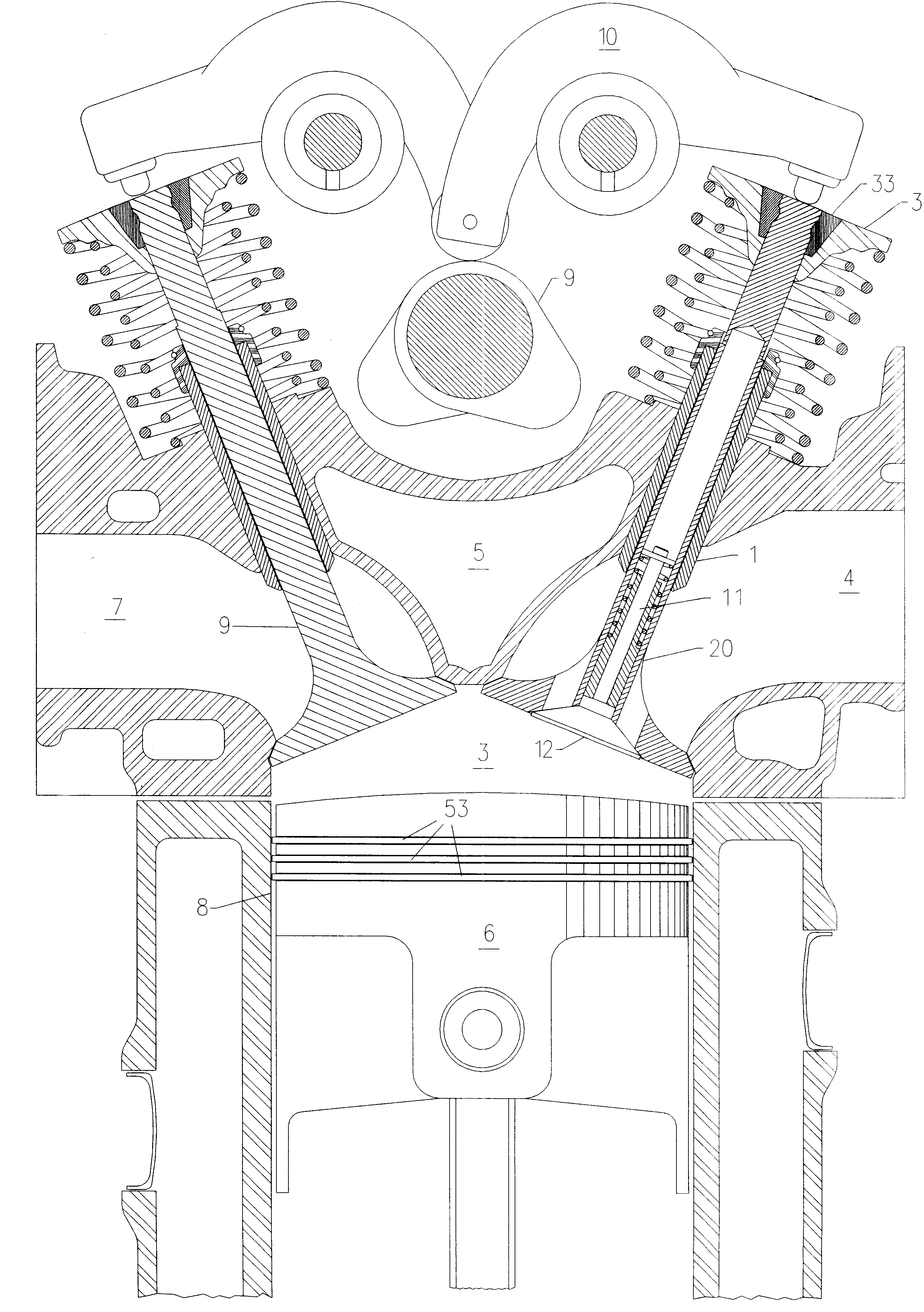
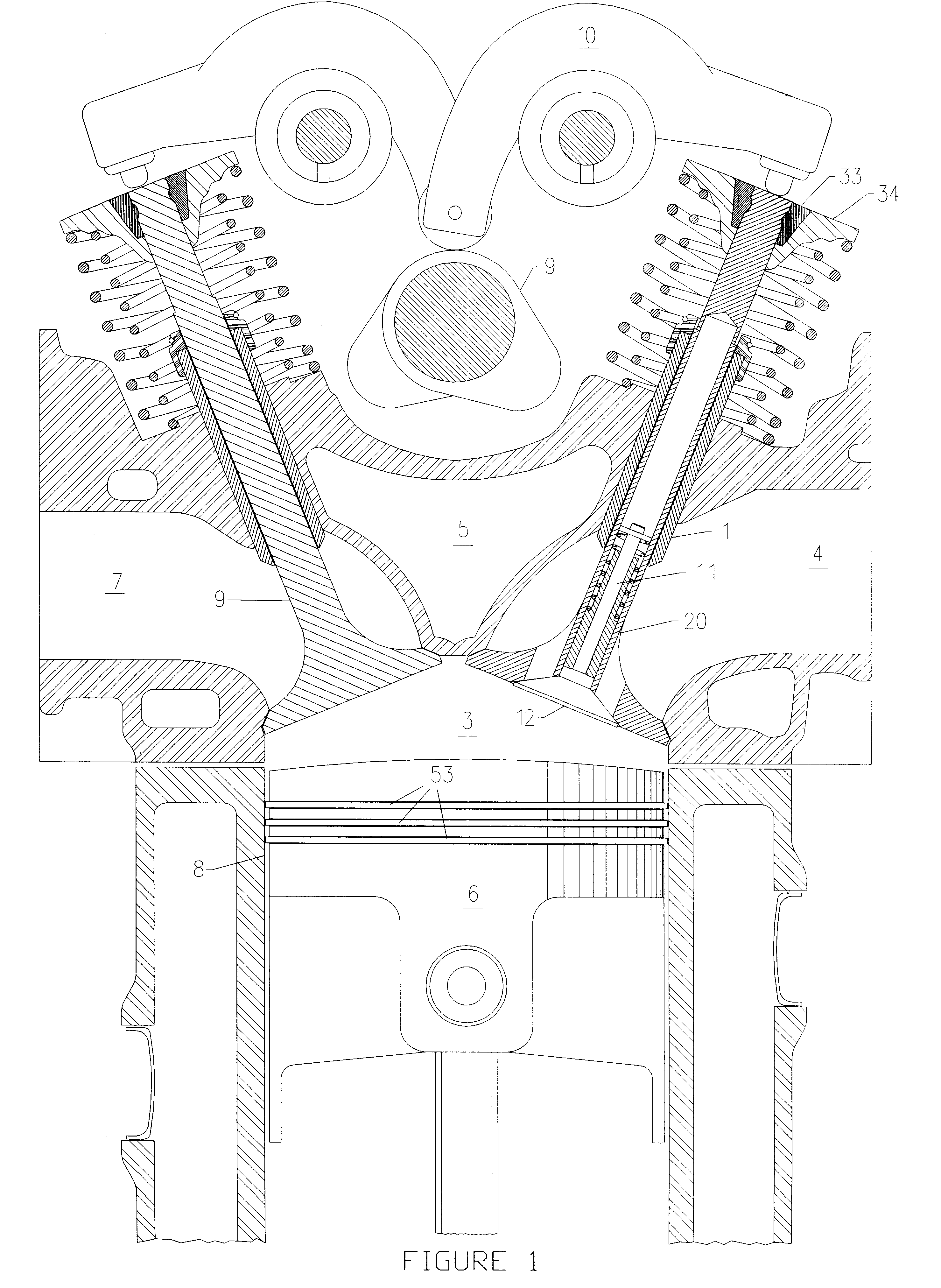
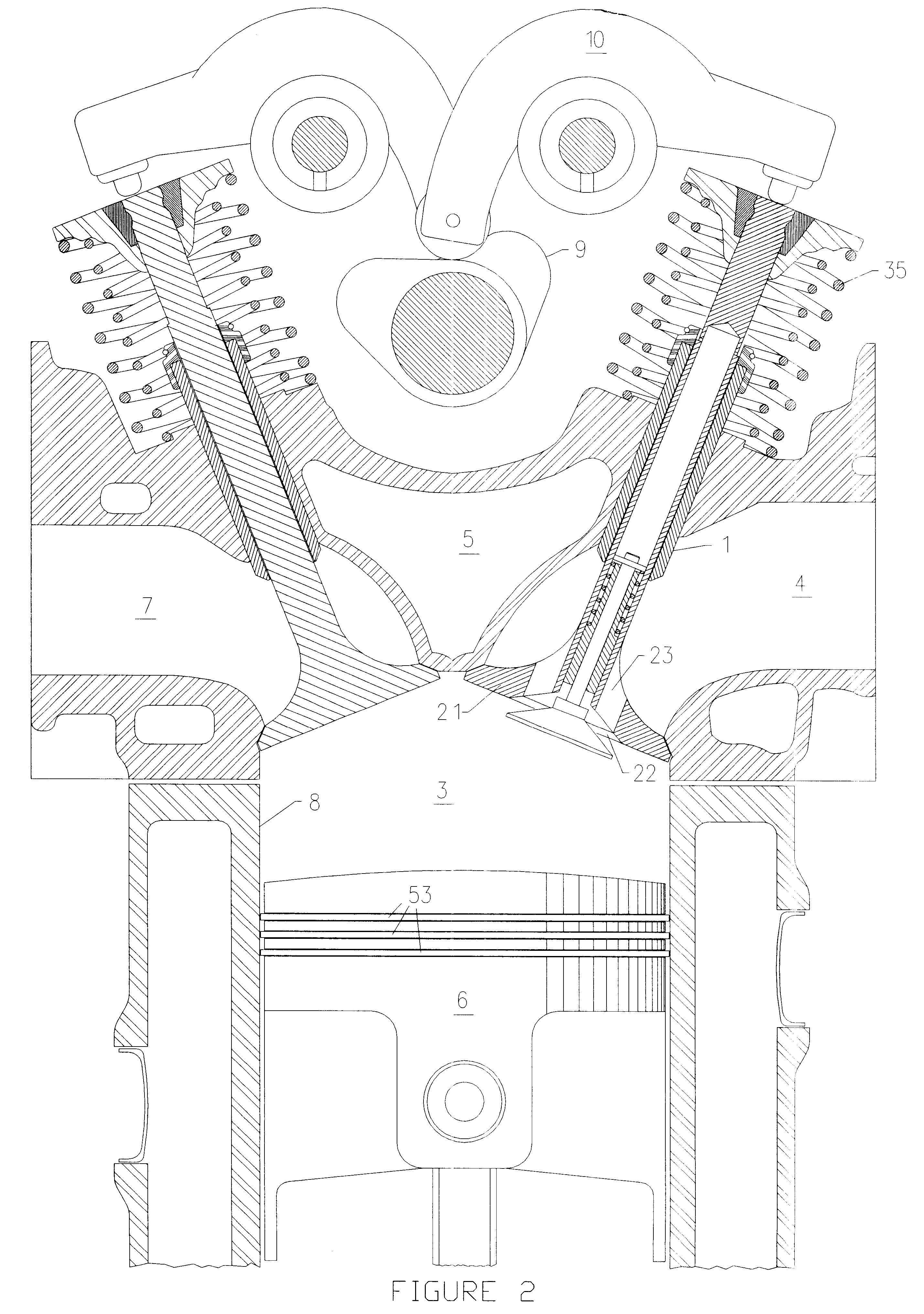
As illustrated by FIGS. 1, 2, 3, & 4, the inner valve stem, FIG. 4-#11, includes an annular retainer, FIG. 4-#40, which can be affixed onto the inner valve stem through various common means such as press fitting or
welding. The inner valve stem, FIG. 4-#11, runs into and through the inner
valve guide, FIG. 4-#14. The inner valve control spring(s), FIG. 4-#41, in a predetermined preload position, acts upon the inner valve retainer, #40, with
constant pressure in the direction of the closed position. The inner
valve guide, FIG. 4-#14, also provides a spring base, FIG. 4-#42, for landing the inner valve control spring, FIG. 4-#41. The inner valve, inner valve guide, spring, and retainer are preassembled as a unit. The outside
diameter of the inner valve guide, FIG. 4-#14, is sized to interfere slightly with the internal
diameter of the hollow portion of the outer valve stem, FIGS. 4 & 8-#31. This allows the entire inner valve control and retention mechanism as a unit to be permanently affixed to the outer valve by pressing the inner valve guide, FIG. 4-#14 into the hollow portion of the outer valve stem, FIGS. 4 & 8-#31, to effectively retain, support, and guide the inner valve member.

